Grounding failure breaker

A ground fault and circuit breaker technology, applied in circuit devices, emergency protection circuit devices, emergency protection devices with automatic disconnection, etc., can solve problems affecting safe use, relay heating, function failure, etc., to achieve energy saving, self- Low energy consumption and improved safety in use

Inactive Publication Date: 2006-06-28
ZHANGJIAGANG HUAJIE ELECTRONICS
View PDF1 Cites 15 Cited by
  • Summary
  • Abstract
  • Description
  • Claims
  • Application Information

AI Technical Summary

Problems solved by technology

In particular, solenoid relays usually require a constant power supply (approximately 120 volts) to switch the solenoid relay and maintain the pull-in state. As a result, the solenoid relay is equivalent to a large power consumption power supply
Also, prolonged power to a s

Method used


Image

  • Grounding failure breaker
  • Grounding failure breaker

Examples


Example Embodiment

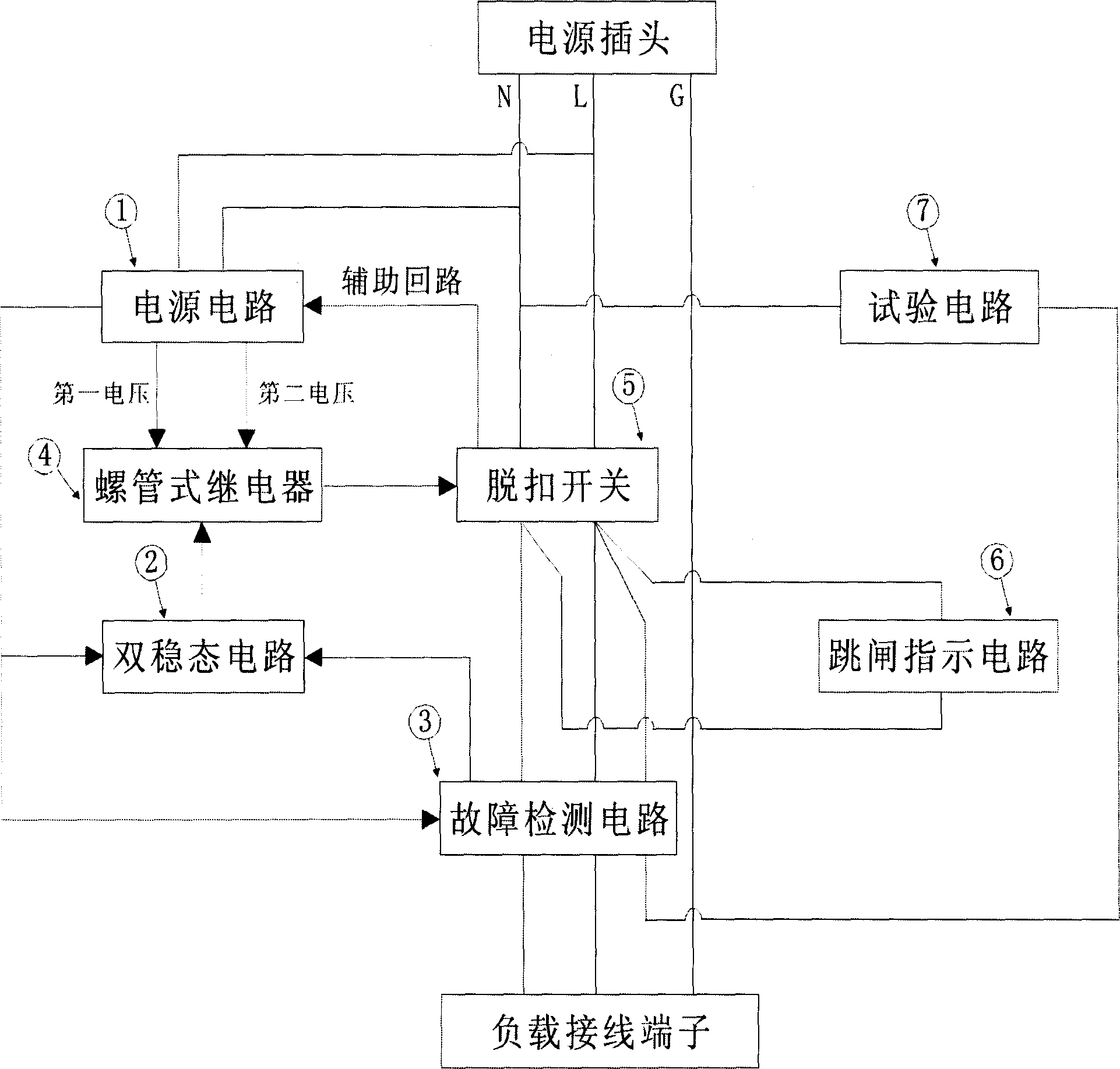
[0025] Such as figure 1 As shown, a ground fault circuit breaker includes: a fault detection circuit 3 and a trip switch 5 arranged on a wire between a power plug and a load connection terminal, and a pair of pairs connected to the fault detection circuit 3 and the solenoid relay 4, respectively. The steady-state circuit 2, the bistable circuit 2, and the solenoid relay 4 are connected to the trip switch 5, and the power circuit 1 connected to the bistable circuit 2, the fault detection circuit 3 and the solenoid relay 4 respectively, set A trip indicating circuit 6 between the two wires and close to the trip switch 5, and a test circuit 7 arranged on both sides of the trip switch 5.

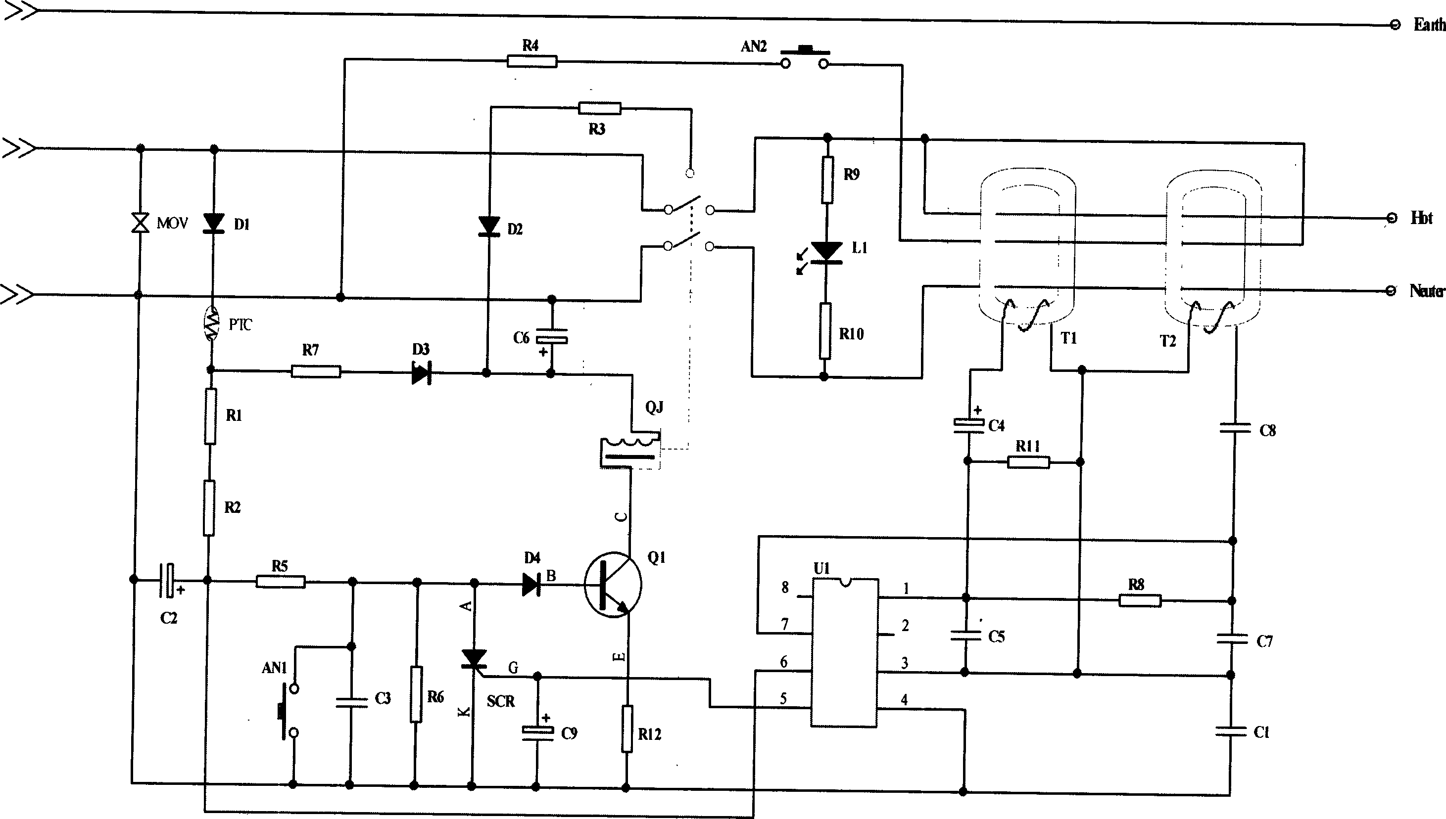
[0026] Such as figure 2 As shown, a ground fault circuit breaker includes a fault detection circuit 3 and a bistable circuit 2. The fault detection circuit 3 consists of a current transformer T1, a neutral transformer T2, an integrated circuit U1, resistors R8, R11, and capacitors C1, C4, C5, C7, a...


PUM

PropertyMeasurementUnit
Wire diameteraaaaaaaaaa

Abstract

This invention relates to an earth fault breaker set between the supply and loads composed of a fault detection circuit, a double stable circuit, a supply circuit, a solenoid relay, a trip switch, a test circuit and a tripping indicating circuit.

Description

technical field [0001] The invention belongs to an electrical safety device, in particular to a leakage fault circuit breaker. Background technique [0002] Conventional electrical appliances are generally connected to the power supply in the socket through wires and power plugs. This simple plug-in has potential dangers such as electric shock and fire to the use of electrical appliances. Electric shock is a grounding fault, which can be life-threatening in severe cases. Electrical fires are generally caused by neutral grounding faults. In such a situation where there are dangerous factors, we need a safer and more reliable leakage fault detection device to ensure the safety of electricity use. [0003] As we all know, products with the above protection functions mainly include: residual current leakage fault protector (abbreviation: "PRCD"), ground fault circuit interrupter (abbreviation: "GFCI" or "A1CI"), etc. For example: U.S. Patent No. 5177657 discloses a ground faul...

Claims


Application Information

Patent Timeline
IPC IPC(8): H02H3/32H02H3/14
Inventor 陆亚洲陈登峰
Owner ZHANGJIAGANG HUAJIE ELECTRONICS
Why Eureka
Try Eureka