Lubricant gun

A sliding box and equipment technology, applied in manual lubricant supply, engine lubrication, mechanical equipment, etc., can solve the problem that the lubricant gun is easily damaged

Active Publication Date: 2006-07-12
LINCOLN INDUSTRIES CORP
View PDF1 Cites 8 Cited by
  • Summary
  • Abstract
  • Description
  • Claims
  • Application Information

AI Technical Summary

Problems solved by technology

Lubricant guns are also vulnerable to damage if the motor overheats due to, for example, a clogged lubricant nipple or an overpressure situation within the pump

Method used


Image

  • Lubricant gun
  • Lubricant gun
  • Lubricant gun

Examples


Embodiment Construction

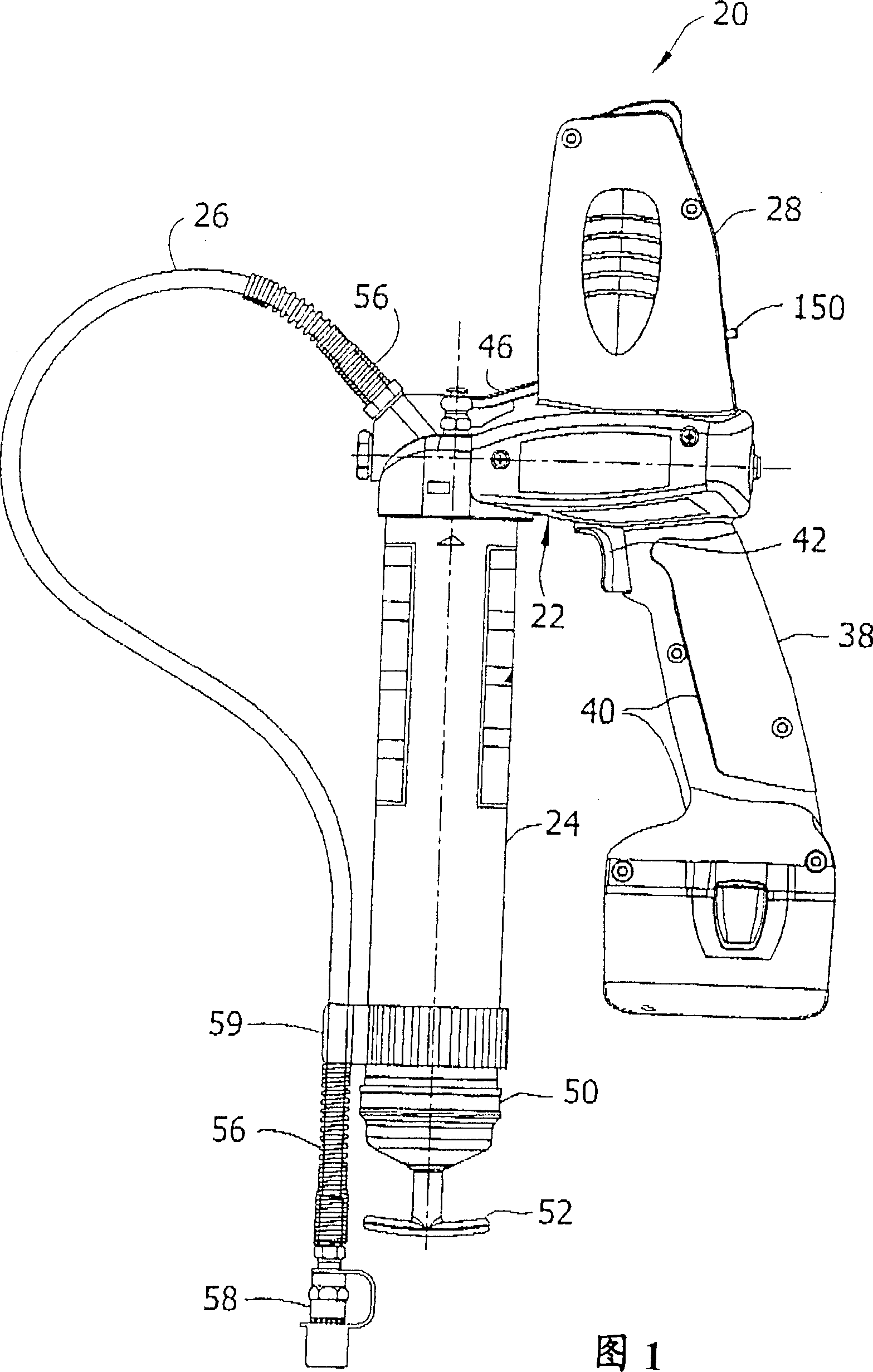
[0035] Referring now to the drawings, and in particular to FIG. 1 , an apparatus for dispensing viscous fluids according to the present invention is indicated generally at 20 . In the embodiment shown in the drawings, the device is a portable hand-held lubricant gun for dispensing lubricant, although other embodiments do not depart from the scope of the invention. Lubricant gun 20 includes a pump mechanism, generally indicated at 22, which delivers lubricant from a reservoir (tank) 24 via a discharge, such as a flexible hose 26, to the machine or vehicle requiring lubrication.

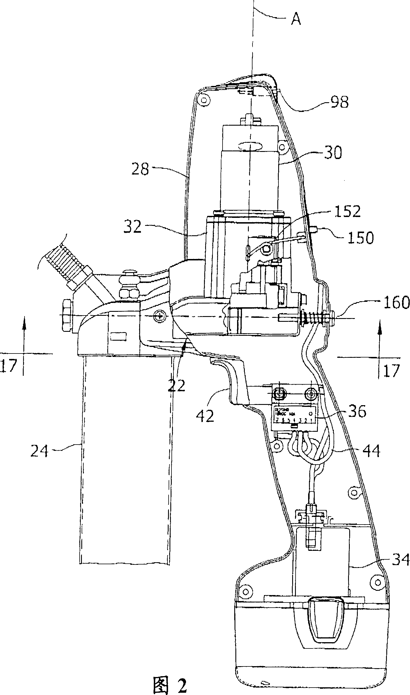
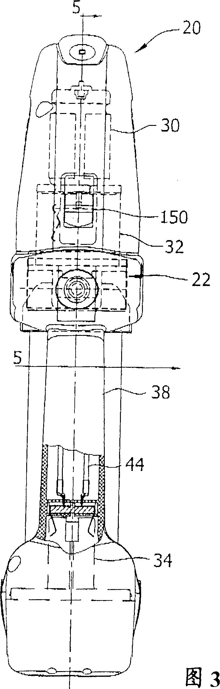
[0036]As shown in FIG. 2, the lubricant gun 20 has a housing 28 that accommodates the pump. Motor 30 and transmission assembly 32 are disposed within housing 28, generally above pump 22, while battery 34 and electrical switch 36 are disposed within housing, generally below the pump. In one embodiment, housing 28 has a clamshell construction made of molded plastic with two side halves held together by ...


PUM


Abstract

A device for dispensing a viscous fluid, such as grease gun for dispensing lubricant. The grease gun delivers lubricant with a selectable variation in pressure and / or output. It includes a reservoir, a pump having a reciprocating plunger, an electric motor driving the pump, and a variable speed transmission for transmitting power from the motor to the pump. The transmission has at least two different output speed settings adapted to be selected for reciprocating the plunger at different cyclical frequencies. A cycle indicator provides an indication corresponding to a quantity of lubricant dispensed. Embodiments of the grease gun include a pressure relief valve which inhibits damage due to an over-pressure condition, and a circuit breaker which inhibits damage due to electrical overload.

Description

technical field [0001] The present invention relates generally to a system for dispensing viscous fluids, and more particularly to an improved lubricator for delivering lubricant to a machine requiring lubrication. Background technique [0002] Hand-held electric lubricators, commonly referred to as "lube guns (grease guns)," have been used extensively to service bearings and other components of vehicles, agricultural equipment, and industrial machinery. Lube guns typically include a pump with a reciprocating plunger, a lubricant reservoir, a discharge hose, and an electric motor to drive the pump. Power the motor through the wire, or power the cordless lube gun with the battery. A transmission assembly having a gear system that converts the rotational motion of the motor shaft to the linear reciprocating motion of the plunger is mounted between the motor and the plunger. The gearing also reduces the rotational cycle frequency of the motor to a lower level to correspond to...

Claims


Application Information

Patent Timeline
Patent Type & Authority Applications(China)
IPC IPC(8): F16N3/08
CPCF16N3/12
Inventor A·格拉奇V·V·阿列克谢耶夫C·霍兰P·康利
Owner LINCOLN INDUSTRIES CORP
Why Eureka
Try Eureka