Sparkle ball holding structure of connector

A connector and solder ball technology, applied in the direction of welding/welding connection, contact parts, etc., can solve the problems of warping and deformation of the circuit board, incomplete flatness, and the circuit board cannot be fully contacted, and achieve the effect of the best welding effect.

Inactive Publication Date: 2006-07-12
林乐贤
View PDF0 Cites 7 Cited by
  • Summary
  • Abstract
  • Description
  • Claims
  • Application Information

AI Technical Summary

Problems solved by technology

[0009] However, as attached figure 2 and attached Figure 4 As shown, the flatness of the surface of the plate-shaped circuit board 4 cannot be maintained in a precise and flat state, and sometimes due to temperature or load, the surface of the circuit board 4 is slightly warped and deformed, and the like is not completely flat.
For the unevenness of the surface of the circuit b

Method used


Image

  • Sparkle ball holding structure of connector
  • Sparkle ball holding structure of connector
  • Sparkle ball holding structure of connector

Examples


Embodiment Construction

[0028] The following descriptions are only preferred embodiments of the present invention, and therefore do not limit the protection scope of the present invention.

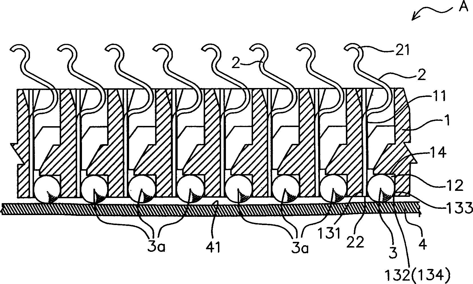
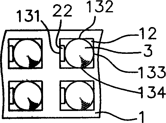
[0029] See attached Figure 5 to attach Figure 9 As shown: the connector B of the present invention still includes an insulating base body 1 , a plurality of terminals 2 , and a plurality of solder balls 3 .

[0030] A plurality of terminal slots 11 penetrate through the insulating base body 1 along its vertical direction. Each terminal 2 is inserted into each terminal slot 11; the upper end and the lower end of these terminals 2 respectively form a contact portion 21 and a welding portion 22; The soldering portion 22 extends downward and protrudes from the bottom of the terminal slot 11 . A plurality of solder balls 3 in a circular state are placed between the insulating base 1 and each soldering portion 22 for soldering with the circuit board 4 .

[0031] The solder ball gripping structure of the present i...


PUM


Abstract

The invention discloses a holding structure for tin ball catcher of connector, which comprises: an insulation base with barrier wall, a plurality of terminals with horizontal tin ball catch hole of open-cone shape on welding part, and multiple tin balls with part located by catch hole and limited by opposite barrier wall and up-and-down slide properly. Wherein, the hole diameter of catch hole is larger a little than the outside diameter of tin ball to catch the ball with a little loose; when welding the connector and circuit board, all tin balls slide up-and-down along contacted board surface to regulate contact evenly and achieve optimal welding effect.

Description

Technical field: [0001] The invention relates to the technical field of connectors, in particular to a grasping structure of a connector. Background technique: [0002] With the advancement of electronic circuits, the number of digits of data processing is getting higher and higher, and the speed is getting faster and faster, so the related connectors have more and more terminal pins. Therefore, the connector composed of many terminal pins plays an important role. [0003] However, the connector with many terminal pins requires soldering technology to be soldered on the circuit board, and when it is applied to surface mount (SMT), it often has a bad situation of open soldering, so it is necessary to improve this open soldering. Adding a solder ball to the soldering part of the terminal of the connector is a solution that has been developed, among which there are two methods of pre-solder ball or embedded solder ball. [0004] as attached figure 1 to attach Figure 4 As s...

Claims


Application Information

Patent Timeline
IPC IPC(8): H01R13/02H01R4/02
Inventor 林乐贤
Owner 林乐贤
Why Eureka
Try Eureka