
Hydraulic pressure adjusting device

An adjustment device, hydraulic pressure technology, applied in the direction of transportation and packaging, brake components, control valves and air release valves, etc., can solve the problems of not shortening the braking distance, lengthening the braking distance, sacrificing the braking force, etc., to achieve good Anti-lock braking function, prevention of sideslip and tail flicking, shortening of braking distance

Inactive Publication Date: 2006-07-19
重庆特锐格科技有限公司
View PDF0 Cites 5 Cited by
  • Summary
  • Abstract
  • Description
  • Claims
  • Application Information

AI Technical Summary

Problems solved by technology

The electronic anti-lock braking device has the following problems: one is that the braking distance cannot be shortened, especially when braking on a road with a small friction coefficient, the braking distance will be lengthened; the other is that the electronic anti-lock braking device The body shakes a lot when starting, which aggravates the resonance phenomenon when the vehicle brakes; the third is that there is a complex electronic control system, which is difficult to install and maintain and expensive
Compared with the electronic anti-lock brake device, the mechanical anti-lock brake device is cheaper and simplifies the system, but when braking, the brake oil is allowed to pass through the rubber body first and expand the output, sacrificing the braking force , can neither shorten the braking distance nor realize the anti-lock function

Method used


Image

  • Hydraulic pressure adjusting device

Examples


Embodiment Construction

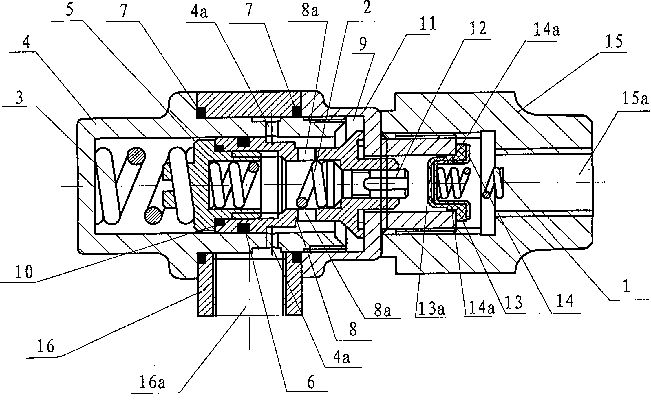
[0019] See figure 1 , The hydraulic pressure adjusting device of the present invention is characterized in that it includes a valve seat 4, a valve cover 11, an end cover 15, an adjusting ring 16, a pressure regulating valve 8, a check seat 14, a check cap 13, and a check valve 12. , The adjusting nut cover 5, the first spring 1, the second spring 2, the third spring 3; the valve seat 4, the valve cover 11, the end cover 15 are threaded in sequence to form an assembly cavity 9, which also serves as a brake The oil path of the oil; the pressure regulating valve 8 is placed on the connecting section of the valve seat 4 and the valve cover 11 of the assembly cavity 9; the check cap 13 is sleeved on the check seat 14 and placed in the assembly cavity 9 The connecting section of the valve cover 11 and the end cover 15, the top of the non-return cap 13 is provided with an oil through hole 13a, the circumference of the non-return seat 14 is provided with an oil through hole 14a; the adju...


PUM


Abstract

The invention discloses a hydraulic pressure adjustment device, which comprises the following parts: valve seat, valve lid, end lid, adjustment ring, adjustment valve, non-return seat, non-return cap, non-return valve, adjustment nut lid, first spring, second spring and third spring, wherein the valve seat, valve lid and end lid are connected into assembly cavity sequently; the adjustment valve, non-return seat, non-return cap, non-return valve, adjustment nut lid, first spring, second spring and third spring are set in the assembly cavity; the adjustment ring is set on the periphery of valve seat. The invention is cascaded on the braking oil-way of vehicle to control the oil feeding time difference and pressure difference for vehicle, which shortens the braking distance to avoid the accident.

Description

Technical field [0001] The invention relates to a hydraulic pressure regulating device. Background technique [0002] Existing hydraulic braking devices for road machinery (such as automobiles) include electronic anti-lock braking devices and mechanical anti-lock braking devices. The electronic anti-lock braking device has the following problems: one is that the braking distance cannot be shortened, especially when braking on a road with a low friction coefficient, it will increase the braking distance; the second is the electronic anti-lock braking device The vehicle body shakes a lot when starting, which aggravates the resonance phenomenon when the vehicle is braking; third, there is a complex electronic control system, which is difficult to install and maintain and expensive. Compared with the electronic anti-lock brake device, the mechanical anti-lock brake device is cheaper and simplifies the system. However, when braking, the brake fluid is allowed to pass through the rubbe...

Claims


Application Information

Patent Timeline
Patent Type & Authority Applications(China)
IPC IPC(8): B60T8/34
Inventor 熊鹰
Owner 重庆特锐格科技有限公司
Learn More