

Cleaning apparatus for air cooling unit
A technology for cleaning devices and air-cooling units, which is applied to cleaning heat transfer devices, cleaning methods using liquids, and non-rotating equipment cleaning. It can solve the problems of high labor intensity and inconvenient operation for workers, and achieve good cleaning effects.
- Summary
- Abstract
- Description
- Claims
- Application Information
AI Technical Summary
Problems solved by technology
Method used
Image

Examples
Embodiment 1
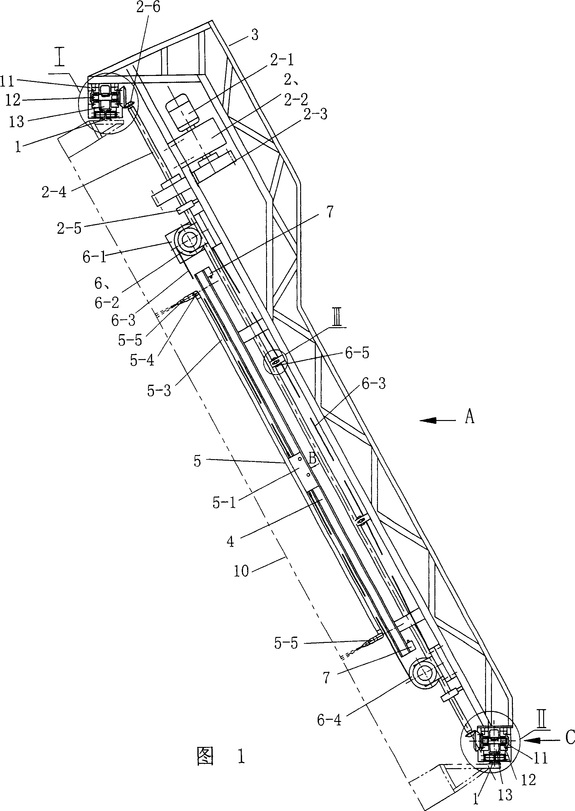
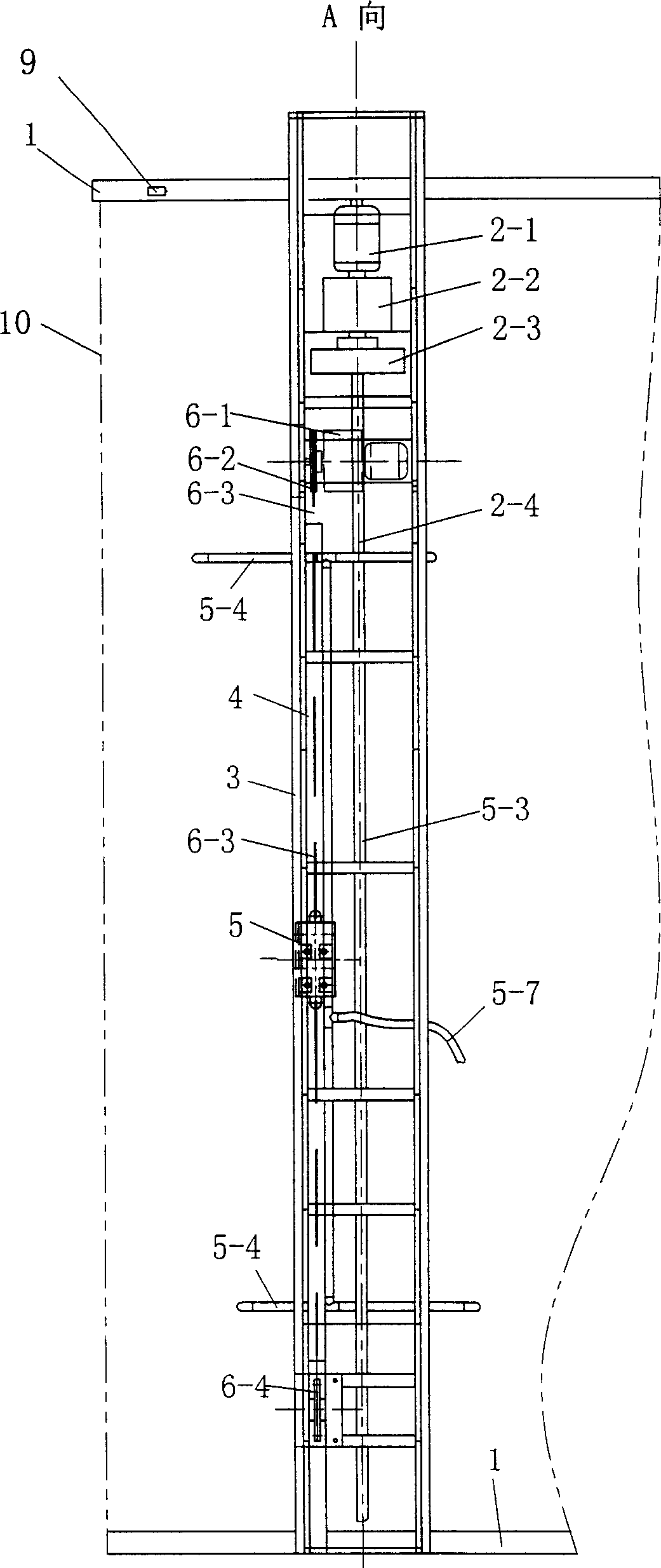
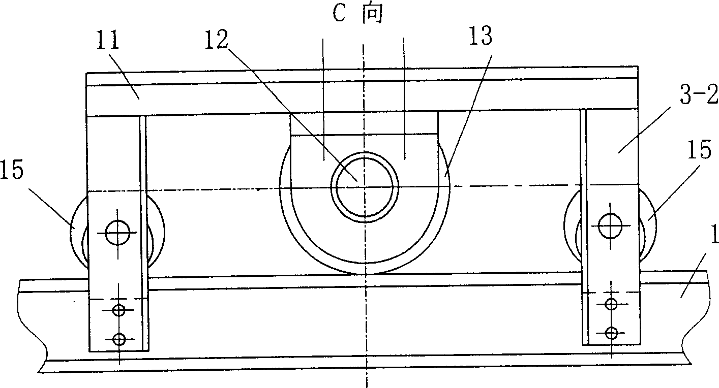
[0034] See Fig. 1~5, present embodiment has upper and lower transverse guide rail 1, and upper and lower transverse guide rail 1 adopts I-beam. The upper and lower transverse guide rails are installed parallel to the radiator 10. A mobile frame 3 is arranged between the transverse guide rails 1, and the upper and lower ends of the mobile frame 3 are respectively provided with a wheel seat 11, and the upper and lower wheel seats 11 are respectively connected to the roller shaft 12 by a bearing 12-1, and the roller shaft 12 is fixed with a roller 13. The rollers 13 on the upper and lower wheel bases 11 are equal in diameter and placed on the upper and lower transverse guide rails 1 respectively, rolling on the top surfaces of the upper and lower transverse guide rails. The upper and lower two wheel bases 11 are respectively provided with anti-side wheels 15 (see image 3 ), the axle of anti-side wheel 15 is to be fixed on the wheel base 11 and be connected by bearing between an...
Embodiment 2
[0043] See Fig. 16, 17, if there is still a section of distance that water can not be sprayed between the nozzle 5-5 on the upper lateral branch pipe of the nozzle assembly and the top of the cooling fin, an upwardly protruding lateral additional water pipe8. The additional water pipe 8 is provided with 3 shower nozzles 8-1, and the additional water pipe 8 is connected with the water pump through the flexible pipe 8-2. The part is cleaned by the water ejected from the shower head 8-1 by the movement of the moving frame 3. The above-mentioned additional water pipe nozzle 8-1 is a linear nozzle. All the other are identical with embodiment 1.
PUM
 Abstract
Description
Claims
Application Information