Reversible overlap operator for efficient lossless data compression

An operator, parameter value technology, applied in the field of digital media compression

Active Publication Date: 2006-07-19
MICROSOFT TECH LICENSING LLC
View PDF0 Cites 12 Cited by
  • Summary
  • Abstract
  • Description
  • Claims
  • Application Information

AI Technical Summary

Problems solved by technology

However, in reality, infinite precision is impossible. For lossless data compression, the requirement is to design transformations that operate on integers or fixed-precision operations, and can only completely reconstruct data represented by integers that give transformation coefficients.

Method used


Image

  • Reversible overlap operator for efficient lossless data compression
  • Reversible overlap operator for efficient lossless data compression
  • Reversible overlap operator for efficient lossless data compression

Examples


Embodiment Construction

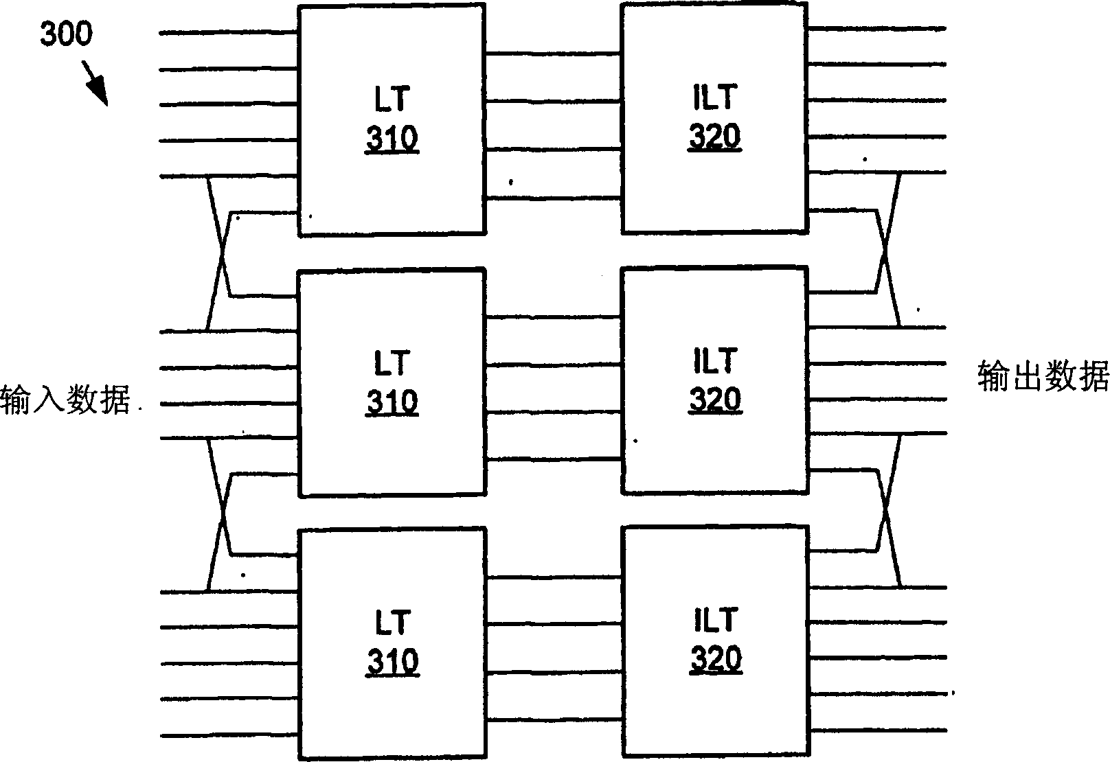
[0052] The following description relates to a digital media compression system or codec that uses a lapped transform using an invertible lap operator. For purposes of illustration, one embodiment of a compression system including a reversible overlap operator is an image or video compression system. Alternatively, the reversible overlap operator can also be included in other compression systems or codecs for 2D data. The reversible overlap operator does not require the digital media compression system to encode the compressed digital media data in a specific encoding format.

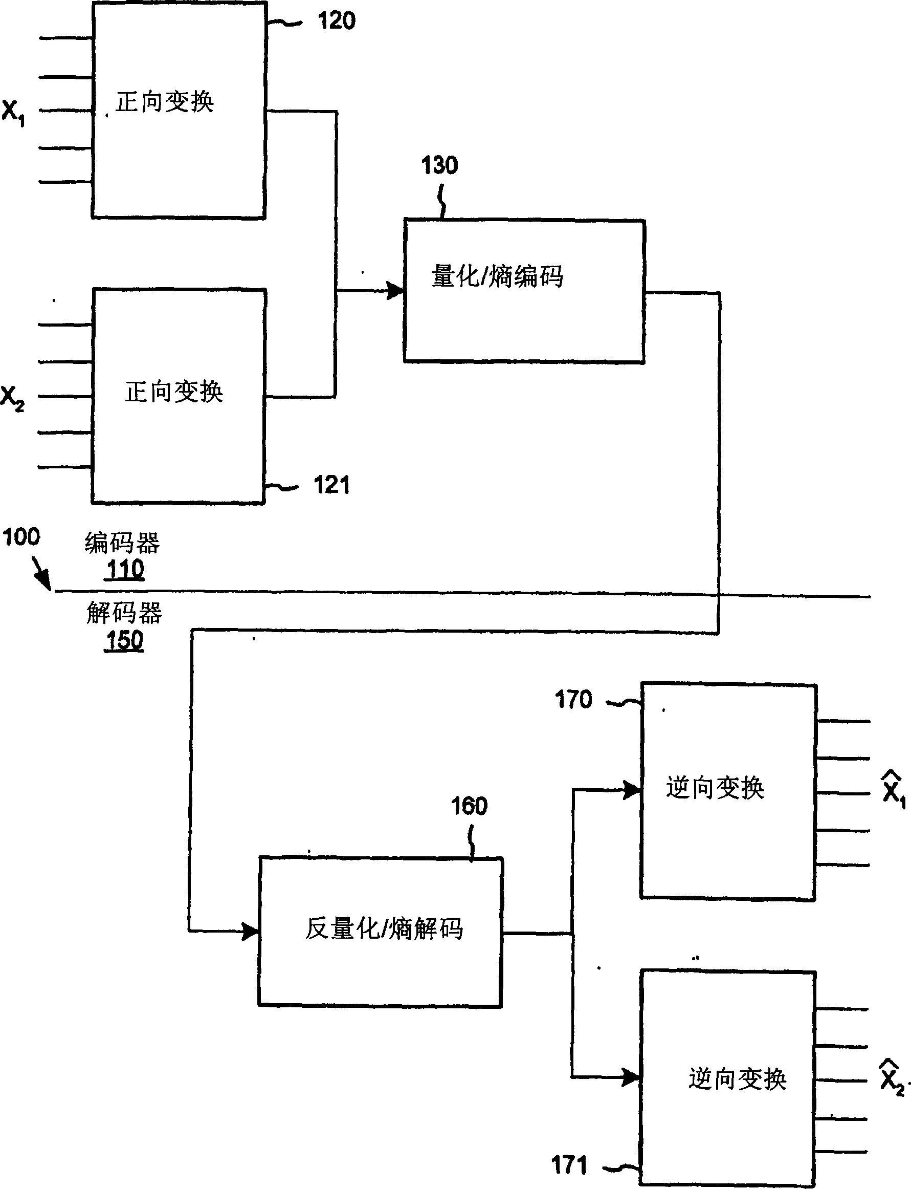
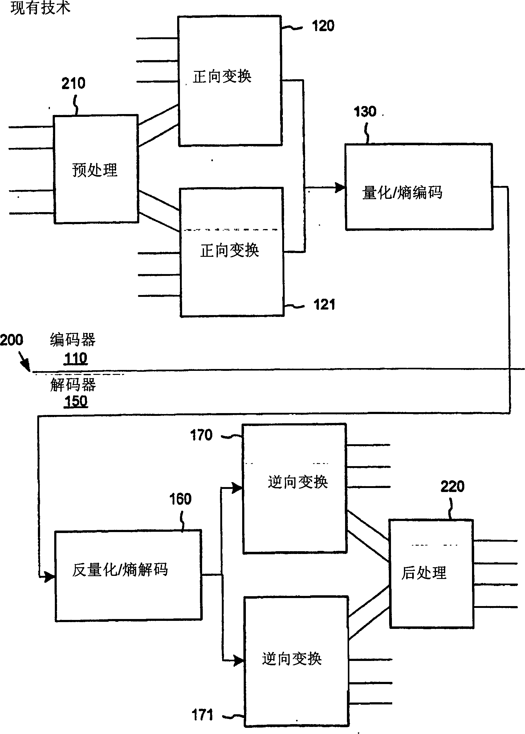
[0053] 1. Encoder / Decoder

[0054] Figure 4 and 5 is a generalized schematic diagram of the process used in a representative 2-dimensional (2D) data encoder 400 and decoder 500 based on a lapped transform using a reversible lap operator. These figures provide a generalized or simplified illustration of the use and application of this reversible overlap operator in compression systems including 2D da...


PUM


Abstract

An efficient lapped transform is realized using pre- and post-filters (or reversible overlap operators) that are structured of unit determinant component matrices. The pre-and post-filters are realized as a succession of planar rotational transforms and unit determinant planar scaling transforms. The planar scaling transforms can be implemented using planar shears or lifting steps. Further, the planar rotations and planar shears have an implementation as reversible / lossless operations, giving as a result, a reversible overlap operator.

Description

technical field [0001] The present invention relates generally to compression of digital media (eg, video and images) using lapped transforms. Background technique [0002] overlapping transform [0003] The lapped transform is a powerful signal processing technique used in data compression. See H.S. Malvar, "Signal Processing with Lapped Transforms", Boston, MA: Artech House Press, 1992. However, an efficient lapped transform with linear phase has not been formulated nor applied to lossless (reversible) compression of data so far. [0004] As discussed in more detail below, it is known that a lapped transform can be formulated as a pre-filter before a data transform (and its inverse transform as an inverse data transform before a post-filter). See e.g. H.S. Malvar in Proc. Picture Coding Symposium, "A pre-and post-filtering technique for the reduction of blocking effects (for reducing the pre- and post-filtering techniques of blocking effects)", Sweden, Stockholm, 1987 6...

Claims


Application Information

Patent Timeline
Patent Type & Authority Applications(China)
IPC IPC(8): H04N7/30
CPCH04N19/00781H04N19/00084H04N19/00818G06F17/147G10L19/0212H04N19/00072H04N19/00775H04N19/00909G10L19/0017H04N19/0089H04N19/119H04N19/122H04N19/80H04N19/86H04N19/63H04N19/61H04N19/60G06F7/52
Inventor 涂承杰H·S·玛尔瓦S·斯里尼瓦杉
Owner MICROSOFT TECH LICENSING LLC
Why Eureka
Try Eureka