

Linkage mechanism of drive-free self-adapting artificial hand
A linkage mechanism and self-adaptive technology, which is applied in the direction of manipulators, chucks, manufacturing tools, etc., can solve the problems of weak self-adaption and inability to realize linkage, etc., and achieve strong self-adaptability, overall weight reduction and stable grip Effect
- Summary
- Abstract
- Description
- Claims
- Application Information
AI Technical Summary
Problems solved by technology
Method used
Image

Examples
specific Embodiment approach 1
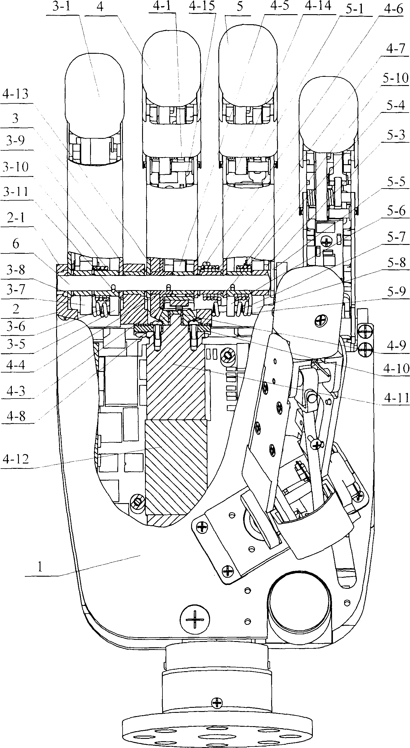
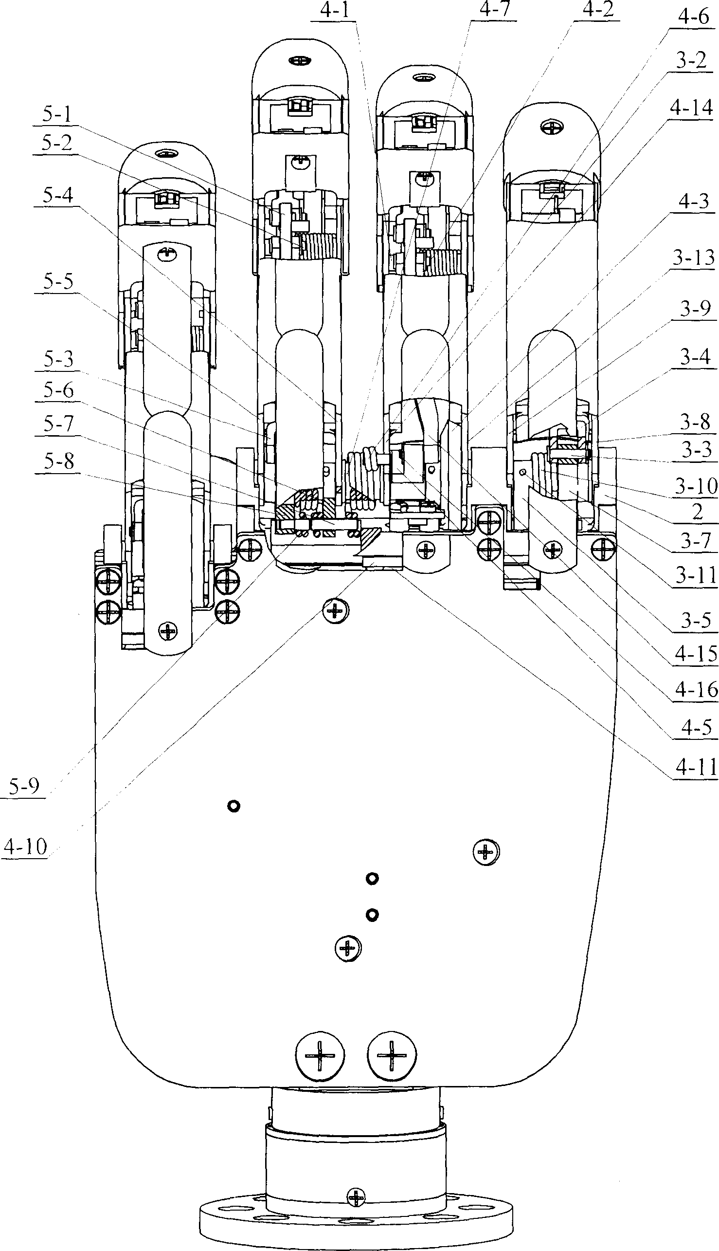
[0007] Specific implementation mode one: combine figure 1 , figure 2 Describe this embodiment, this embodiment is made up of palm 1, the base 2 that is fixedly connected with palm 1, the little finger 3 that is contained in the groove of base 2 in turn, ring finger 4 and middle finger 5, base joint shaft 6; The little finger 3 is by the little finger tip shaft 3-2 connected with the little finger tip 3-1, the little finger connecting rod pin shaft 3-3, the little finger connecting rod 3-4, the spring support 3-5, the spring stop pin 3-6 , little finger torque sensor 3-7, little finger left side plate 3-8, little finger right side plate 3-9, little finger torsion spring 3-10; described ring finger 4 is made up of the ring finger fixed on the middle joint shaft 4-1 of the ring finger Middle joint connecting rod pin 4-2, large bevel gear 4-3, large bevel gear bushing 4-4, ring finger torque sensor 4-5, ring finger torsion spring 4-6, ring finger torsion spring sleeve 4-7, small...
specific Embodiment approach 2
[0009] Specific embodiment 2: This embodiment is described in conjunction with the drawings. The difference between this embodiment and specific embodiment 1 is: the little finger 3 of this embodiment also has a spring support positioning pin 3-11; the spring support 3-5 The positioning pin 3-11 of the spring support is fixedly connected with the base joint shaft 6. The above-mentioned structure has the advantages of simple structure, safe and reliable use.
[0010]Working principle: the output shaft of the motor 4-12 drives the reducer 4-11 to rotate, the output shaft of the reducer 4-11 drives the small bevel gear 4-8 to rotate, and the small bevel gear 4-8 drives the large bevel gear 4-3 to move; The movement of the large bevel gear 4-3 drives the base joint shaft 6 to rotate through the large bevel gear bushing 4-4, thereby driving the spring support 3-5 of the middle finger 5 and the little finger 3 and the spring support 5-6 of the middle finger to move, and the spring s...
PUM
 Abstract
Description
Claims
Application Information