Concavo-convex gear type rotor engine

A rotary engine and gear-type technology, applied to combustion engines, machines/engines, internal combustion piston engines, etc., can solve the problems of insufficient combustion of the mixture, poor sealing performance of the cylinder block, low fuel efficiency, etc., and achieve complete combustion and work Smooth, uniform output power effect

Inactive Publication Date: 2006-07-26
赵耀芝
View PDF0 Cites 1 Cited by
  • Summary
  • Abstract
  • Description
  • Claims
  • Application Information

AI Technical Summary

Problems solved by technology

High-speed and frequent ignition widens the induction period (or after-ignition period), resulting in insufficient combustion of the mixture and low fuel efficiency
Moreover, due to the limitation of the structure, the sealing performance of the cylinder is poor

Method used


Image

  • Concavo-convex gear type rotor engine
  • Concavo-convex gear type rotor engine
  • Concavo-convex gear type rotor engine

Examples


Embodiment 1

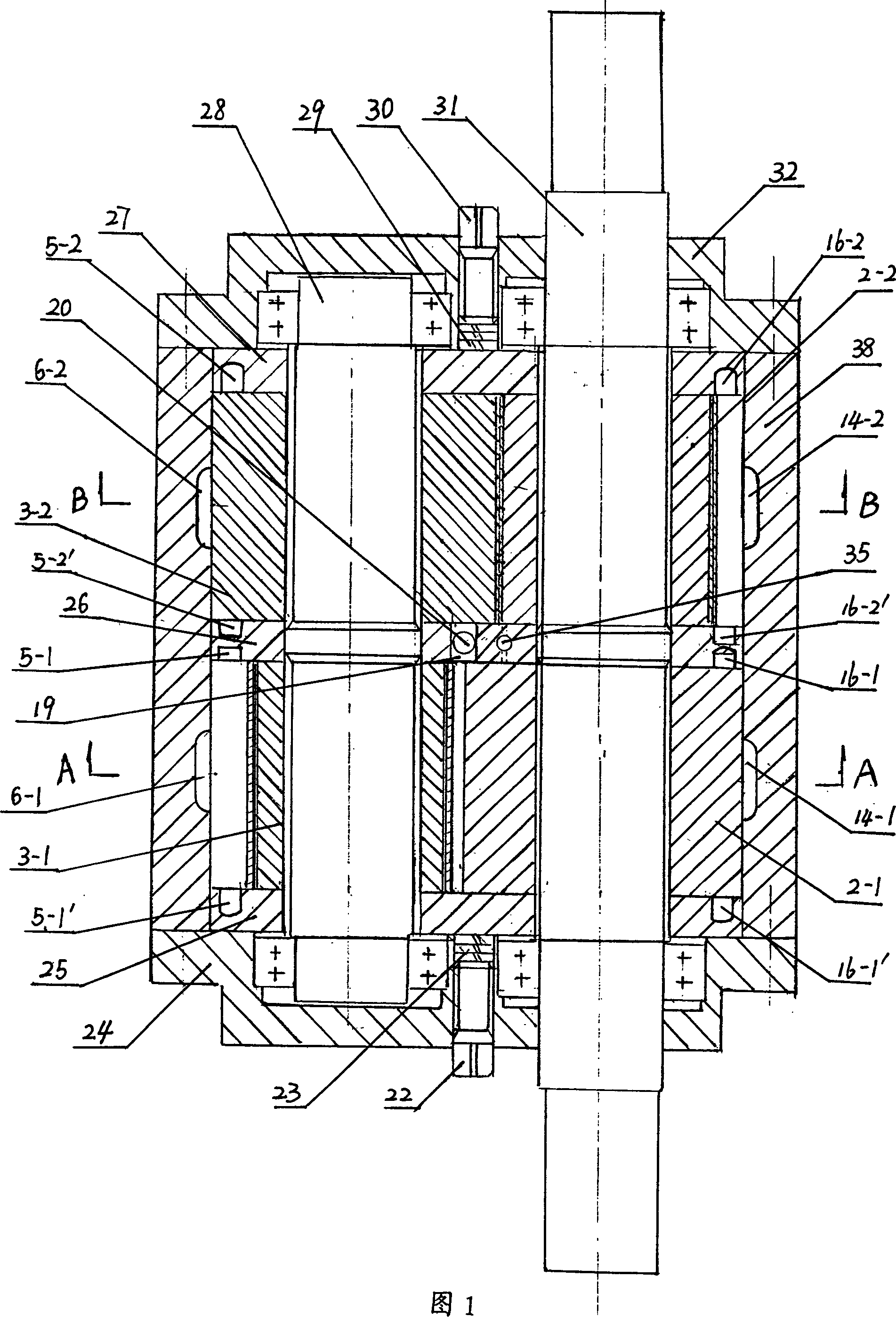
[0035] Example 1: A twin-cylinder engine composed of 8 concave tooth rotors and 6 convex tooth rotors

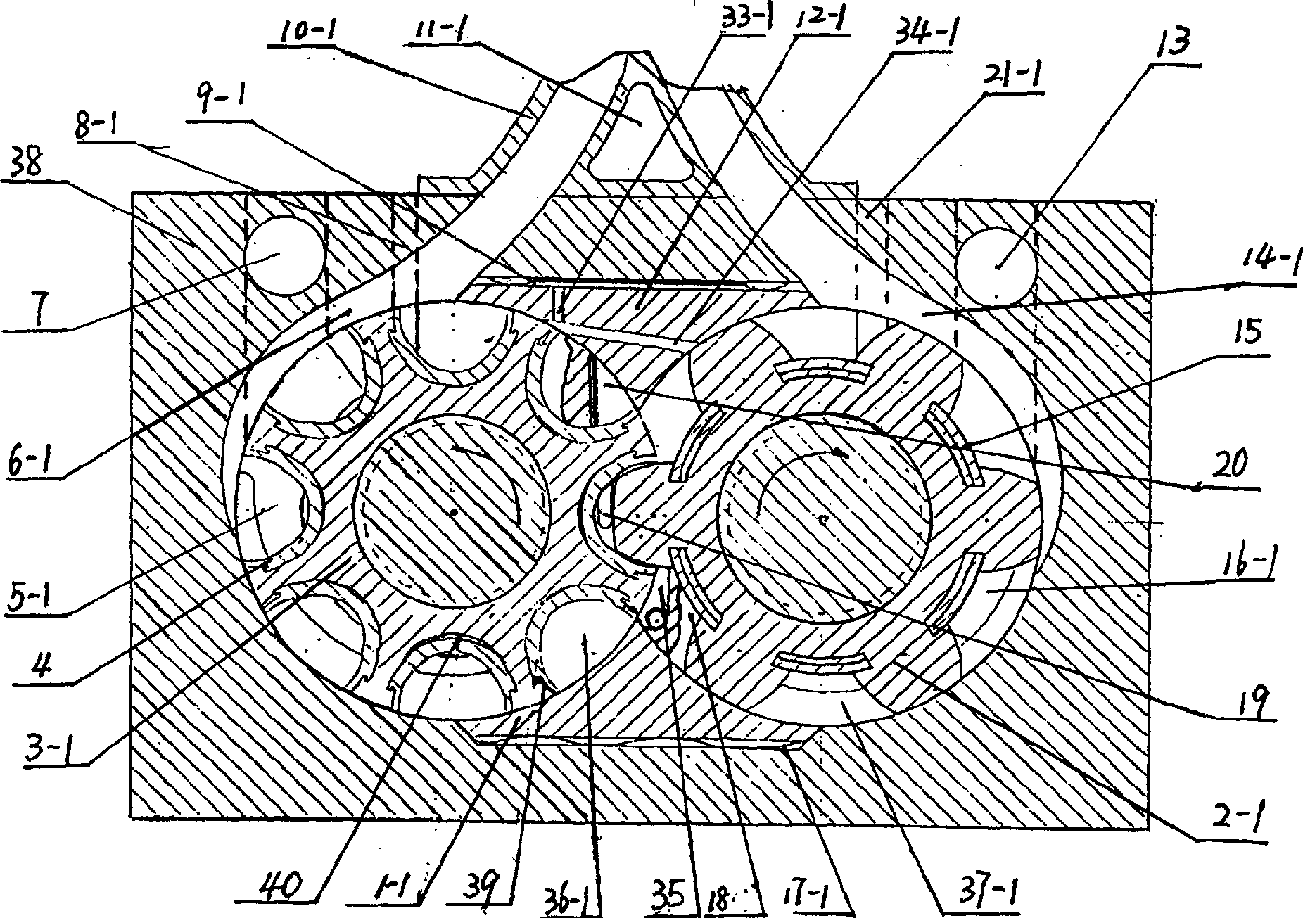
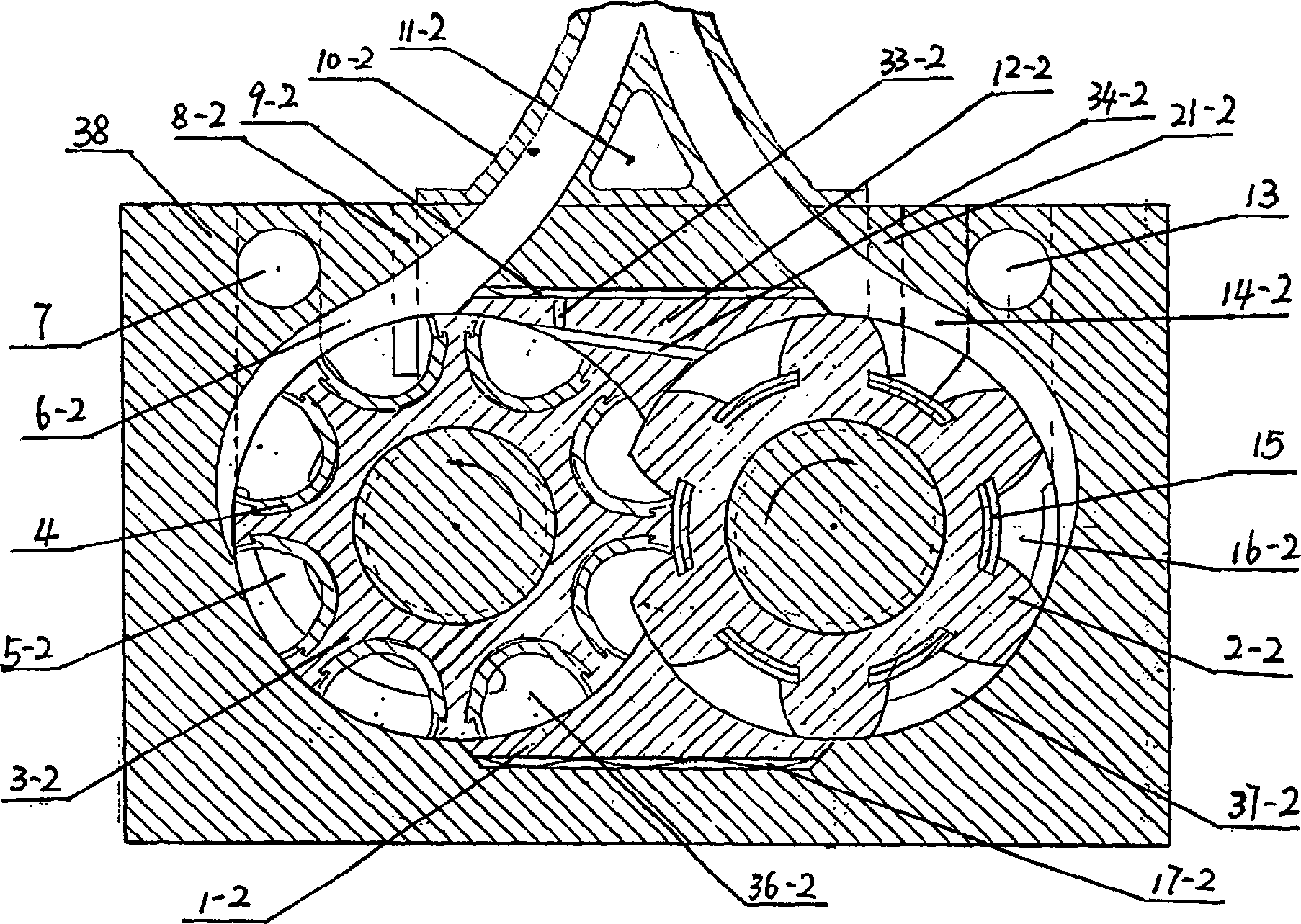
[0036] Fig. 1 is the cross-sectional view of the double-cylinder convex-concave gear rotor engine of the present invention, the two ends of cylinder body 38 are respectively provided with outer end caps 24,32, are respectively provided with inner end caps 25,27 inside two outer end caps, cylinder body A main shaft 28 and an auxiliary shaft 31 are arranged inside, and a back pressure spring 23 is fixed by an adjustment bolt 22 at the joint between the outer end cover and the inner end cover between the main shaft and the auxiliary shaft, and a back pressure spring 29 is fixed by an adjustment bolt 30 . The inside of the cylinder body is divided into two cavities A and B with the same structure by the middle partition 26, and the middle partition, the inner end cover and the back pressure spring realize axial sealing. figure 2It is the A-A sectional view of cylinder A. In cyli...

Embodiment 2

[0045] Embodiment 2 is a four-cylinder engine composed of 8 concave-toothed rotors and 6-convex-toothed rotors with two cylinders for power and two cylinders for compression. The structure and working process of the two cylinders in the middle are basically the same as those in Embodiment 1, and a Press the cylinder.

[0046] Figure 5 It is a cross-sectional view of a four-cylinder convex-concave gear rotor engine. Outer end covers 24 and 32 are respectively arranged at both ends of the cylinder body 38, inner end covers 25 and 27 are respectively arranged inside the two outer end covers, and a main shaft is arranged in the cylinder body. 28 and auxiliary shaft 31, the outer end cover between the main shaft and the auxiliary shaft and the inner end cover joint are fixed with back pressure spring 23 by adjusting bolt 22, and are fixed with back pressure spring 29 by adjusting bolt 30. The inside of the cylinder body is divided into four cavities A2 cylinder, A1 cylinder, B1 c...


PUM


Abstract

The invention relates to a concave-convex rotor motor, which can supply a motor with better sealing, fully burned fuel, simple structure and stable operation. Two ends of cylinder individually comprises the outer end cover, inner end cover, main axle and auxiliary axle; the inner space of cylinder via the middle baffle plate is divided into at least chambers in same structure, while each chamber is in reverse-8 shape and concentric with the main and auxiliary axles; the main axle of each chamber is connected to a convex-teeth rotor with U-shape sheath; the auxiliary axle is connected to a concave-teeth rotor whose teeth root has a rolling sealing sheet; the tops of said concave-teeth rotor and convex-teeth rotor are slide connected to the inner wall of said chamber; the phase difference between two concave-teeth rotors in two chambers and the phase difference are 180 degree/teeth number; and the middle baffle plate has a spark plug and a fire guide hole. The invention has stable operation, lower noise, improved abrasion degree, prolonged service life, reduced fire delay and better safety.

Description

technical field [0001] The invention relates to an engine, more specifically, to a rotary engine in which there are at least two cylinders in the cylinder and the two meshing rotors are respectively corresponding convex teeth and concave teeth. Background technique [0002] At present, in the existing rotary engine, because the rotor and the cylinder are not concentric, during the rotation process, the impact force of the rotor on the cylinder is large, and there is a hysteresis force, which makes the engine work unstable, with large vibration and noise, and serious wear and tear. , internal consumption part of the work. Moreover, during the high-speed operation of the existing rotary engine, spark plug ignition is required for each working cycle. High-speed and frequent ignition widens the induction period (or ignition lag period), resulting in insufficient combustion of the mixture and low fuel efficiency. Moreover, due to structural limitations, the sealing performance ...

Claims


Application Information

Patent Timeline
Patent Type & Authority Applications(China)
IPC IPC(8): F02B53/02
CPCY02T10/17Y02T10/12
Inventor 赵耀芝
Owner 赵耀芝
Why Eureka
Try Eureka