

Wind-driven machine
A technology of wind turbines and wind tunnels, applied in the direction of wind power engines, engines, machines/engines, etc., can solve the problems of not improving the utilization rate of wind energy, single blade structure, low utilization rate of wind energy, etc., achieving remarkable environmental protection and social benefits, Increased wind energy efficiency and strong air volume
- Summary
- Abstract
- Description
- Claims
- Application Information
AI Technical Summary
Problems solved by technology
Method used
Image

Examples
Embodiment 1
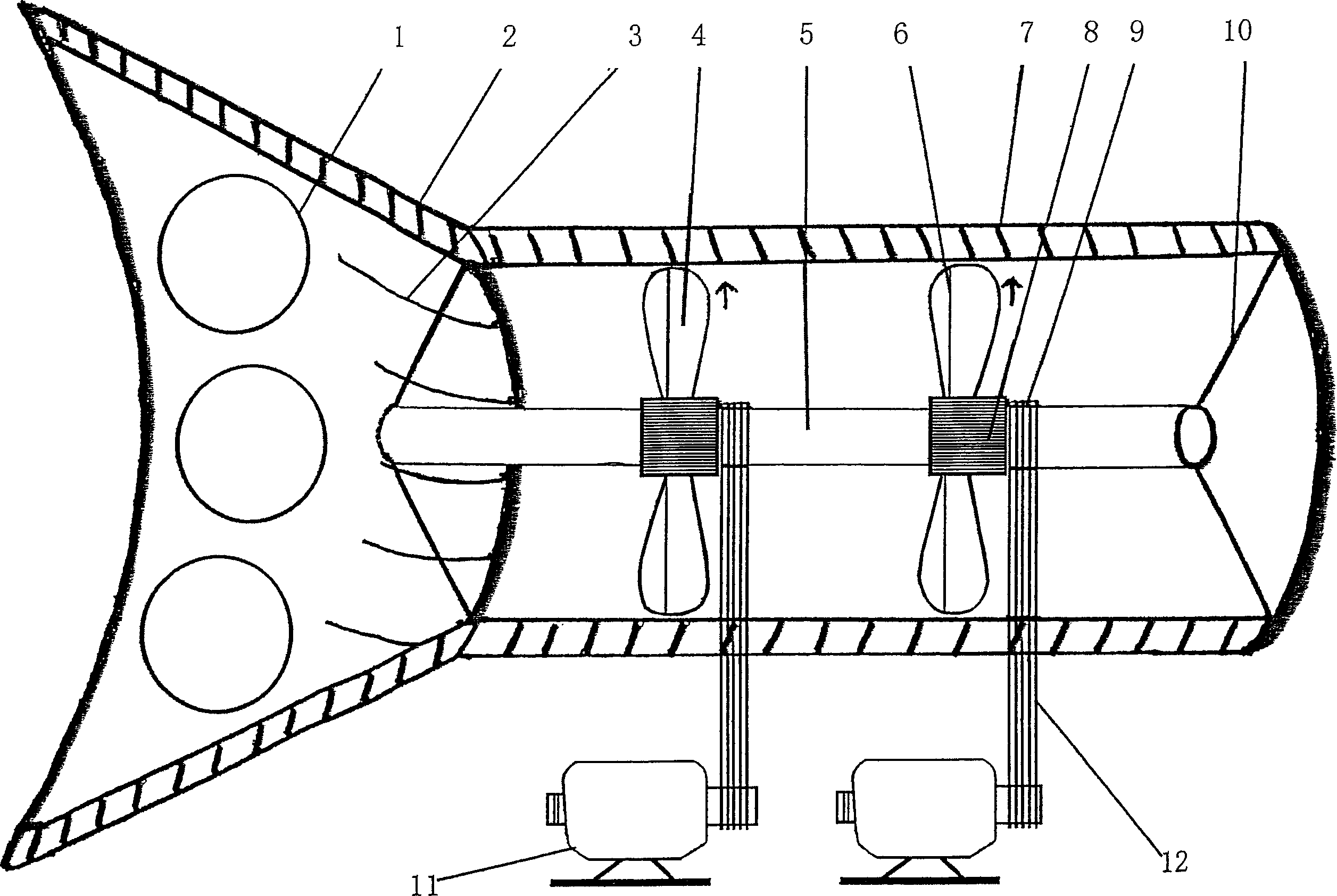
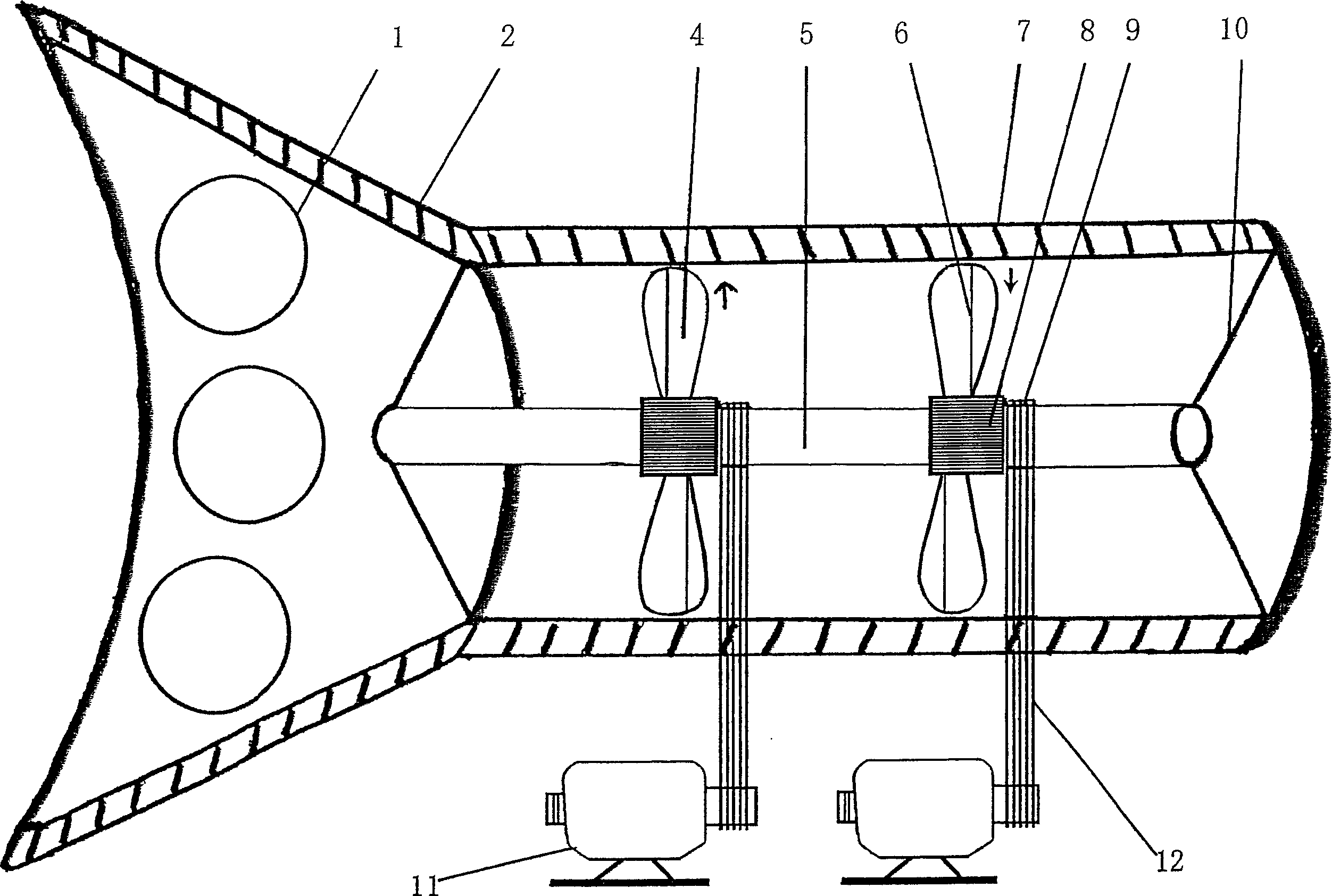
[0022] As shown in the figure, a kind of wind machine described in the present invention, it is made up of wind gathering cover 2, cyclone guide channel 3, wind tunnel 7, blade 4 and shaft 5 etc., is characterized in that wind gathering cover 2 and wind The holes 7 are connected into one body, and both ends of the wind tunnel are provided with shaft brackets 10, the shaft brackets 10 are integrated with the shaft 5, the impeller 8 on the shaft 5 is connected with the pulley 9, and the pulley 9 is provided with a belt 12, The belt 12 is connected with the gearbox 11 .
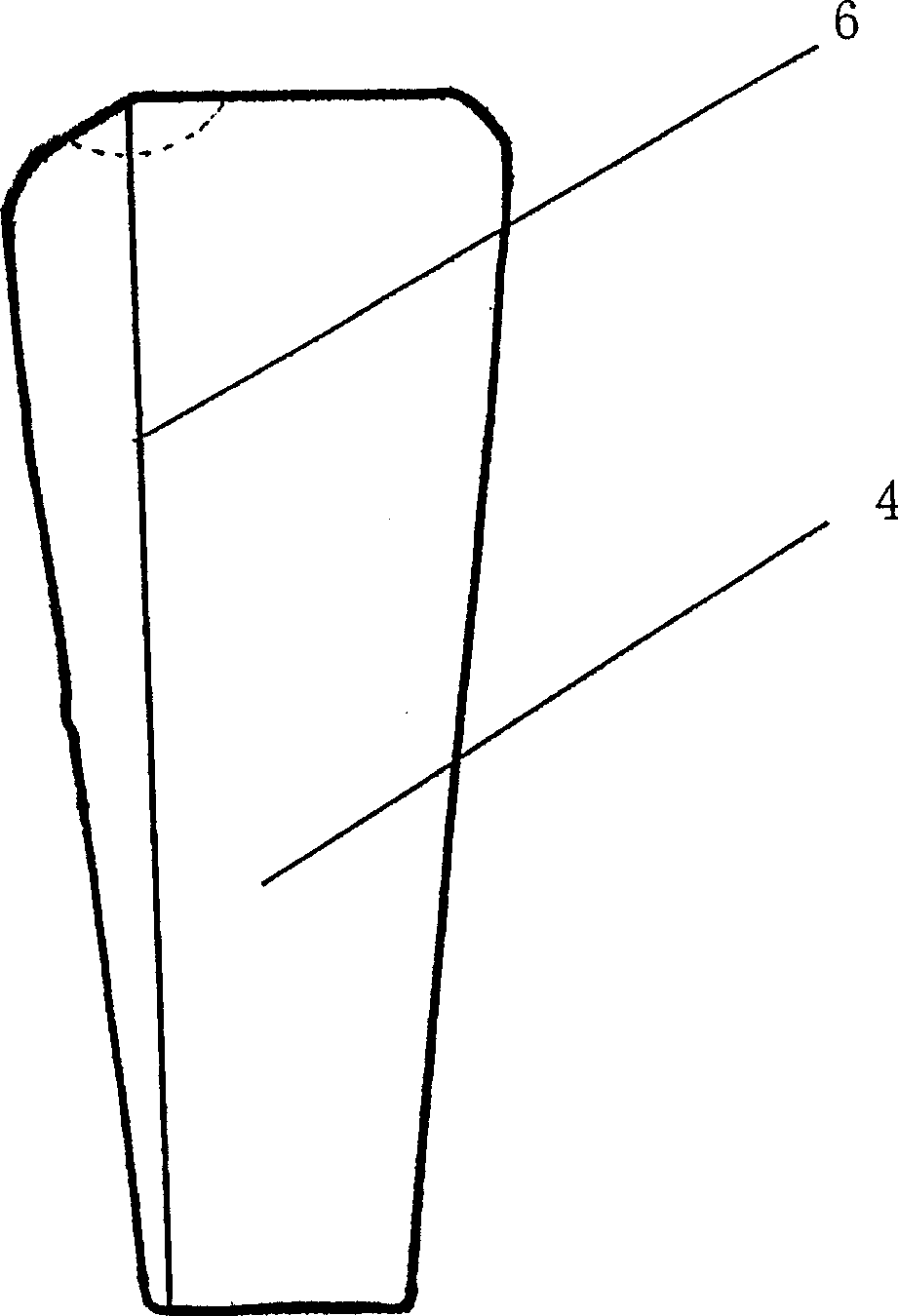
[0023] Such as Figure 1-Figure 3 As shown, the blade 4 of the present invention is provided with a blade angle 6, and the blade angle 6 on the blade 4 can be set at different positions during implementation, that is, it can be located on the left side of the blade 4, or it can be located on the left side of the blade 4. On the right side, for example, the impellers 8 in the wind tunnel 7 can rotate in the same...
PUM
 Abstract
Description
Claims
Application Information