
Femtosecond laser camera

A femtosecond laser and camera technology, applied in the direction of instruments, etc., can solve the problem that the pulse width cannot be directly given

Inactive Publication Date: 2006-07-26
CHINA JILIANG UNIV
View PDF1 Cites 7 Cited by
  • Summary
  • Abstract
  • Description
  • Claims
  • Application Information

AI Technical Summary

Problems solved by technology

[0013] Since the SPIDER method does not have high requirements on the energy of the optical pulse, it can be detected directly from the output of the laser oscillation stage (no optical power amplification stage), and its processing operation for reconstructing the pulse phase does not require an iterative algorithm, is simple and fast, and can be used as a real-time A tool for detecting phase information of optical pulses, but this method cannot directly give information such as pulse width

Method used

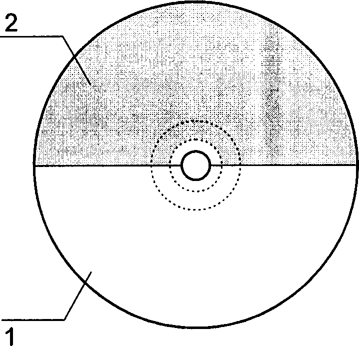
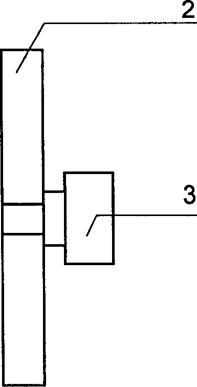

Image

  • Femtosecond laser camera
  • Femtosecond laser camera
  • Femtosecond laser camera

Examples


Embodiment Construction

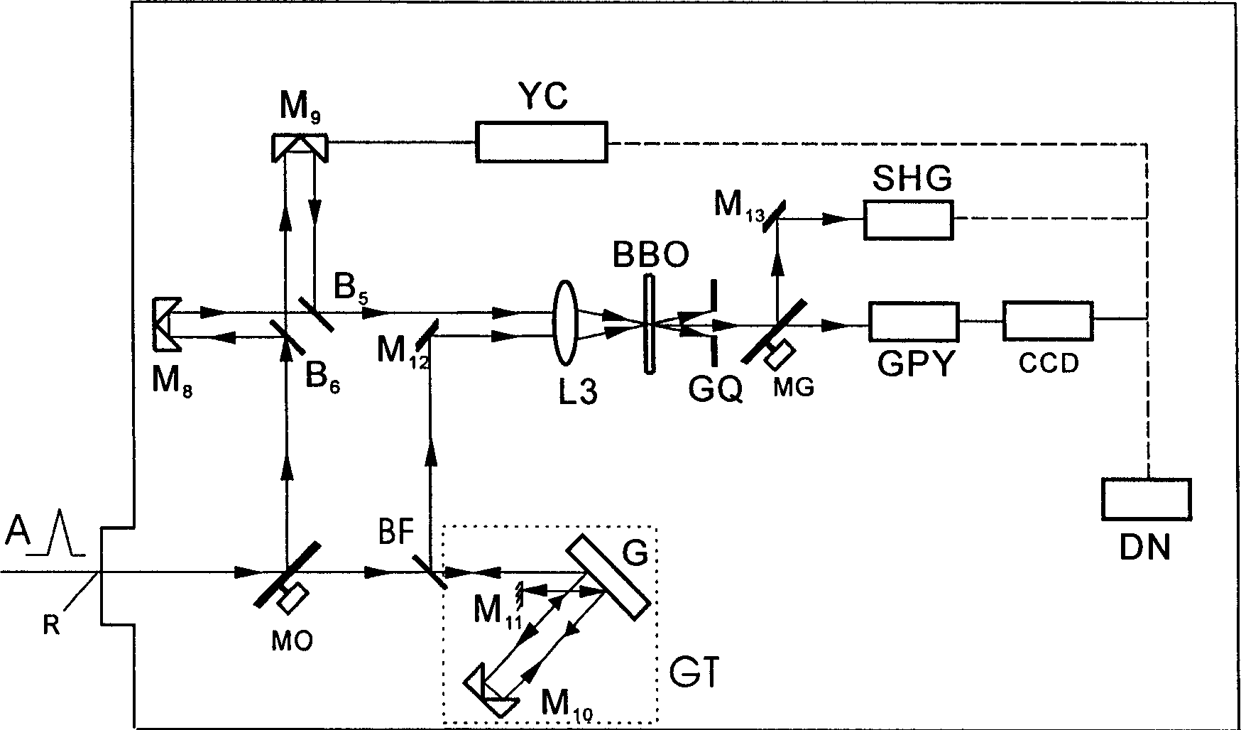
[0037] like figure 1 As shown, the femtosecond laser camera has a laser pulse input port R (generally a hollow aluminum tube with a black-plated inner wall, which is used as the introduction path of the measured laser pulse, and is integrated with the mode converter MO), along the input The input direction of the measured laser pulse at the port is sequentially provided with a mode converter MO, which transmits the other mirror BF and the spectral phase modulator (stretcher) GT on one side, and transmits the laser pulse direction reflected by the other mirror BF on one side and A mirror M that transmits laser pulses to the focusing lens L3 is arranged between the focusing lenses L3 12 . Michelson interferometer [including right-angle mirror M 8 , a movable right-angle mirror M arranged at right angles to the mirror 9 (Part of the time delay shutter YC) and beam splitter (also known as half mirror) B 6 , B 5 ], and in the direction of the laser pulse output by the Michels...


PUM


Abstract

The invention relates to device for measuring the characteristics of femtosecond pulse laser. The device comprises: a femtosecond laser camera; along laser pulse direction of the camera laser input port are in sequence installed a mode converter, a mirror which one side for transmission and the other side for reflection, and a spectrum phase modulator; a focusing lens; a Michelson interferometer with a time delay shutter, which is installed in the reflected laser pulse direction along the laser input port of the mode converter, and the focusing lens, frequency doubling crystal, space filtering diaphragm, gain selecting switch, light spectrum instrument and video camera which are installed in sequence; an interference autocorrelation receiver SHG is installed in the direction of laser pulse reflected by the gain selecting switch; also includes a computer.

Description

technical field [0001] The invention relates to a device for measuring ultrashort pulse laser, in particular to a device for femtosecond pulse laser capable of accurately measuring pulse width, quickly measuring phase, chirp and other characteristics. Background technique [0002] At present, ultrashort pulse laser generally refers to the pulse width less than picosecond (ps, 10 -12 second) level of laser light. Since the advent of lasers in the 1960s, the initial ultrashort pulse laser was a few nanoseconds (ns, 10 -9 second) width of light, by the 1990s, due to the invention of Kerr lens mode-locking and soliton mode-locking technology, and the use of new broadband laser media (such as titanium-doped sapphire Ti:Al 2 o 3 ) solid-state self-mode-locked lasers can already directly generate several femtoseconds (fs, 10 -15 seconds) width of light. Femtosecond pulsed lasers have been widely used in the research of various ultrafast phenomena and physical behaviors under s...

Claims


Application Information

Patent Timeline
Patent Type & Authority Applications(China)
IPC IPC(8): G01J11/00
Inventor 刘天夫
Owner CHINA JILIANG UNIV
Learn More