Heat radiation design of backlight module

A backlight module and light source technology, applied in optics, nonlinear optics, instruments, etc., can solve problems such as inability to form uniform temperature distribution, affect the uniformity of reflected light, and inability to adjust heat dissipation speed, etc.

Inactive Publication Date: 2006-07-26
IND TECH RES INST
View PDF2 Cites 9 Cited by
  • Summary
  • Abstract
  • Description
  • Claims
  • Application Information

AI Technical Summary

Problems solved by technology

Since the brightness of the fluorescent tube is mainly affected by the temperature, if the temperature continues to rise and change, the brightness of the fluorescent tube will change with the temperature, which will directly affect the display results; in addition, the display is installed vertically in most cases, and the display is located on the top. In addition to the heat emitted by the fluorescent tube itself, the fluorescent tube also absorbs the heat generated by the fluorescent tube below, which makes the temperature distribution of each fluorescent tube uneven, resulting in uneven brightness
[0005] Therefore, there are heat dissipation designs of different structures to meet the heat dissipation requirements of the backlight module. For example, US6417832 connects each fluorescent tube with a heat conduction bracket, utilizes the heat conduction effect of the heat conduction bracket itself to generate heat exchange between each fluorescent tube, and according to the temperature of each fluorescent tube The horizontal height of the display after it is placed upright, and corresponding ventilation holes (louvers) are opened, because the heat convection effect makes the hot air rise, so the fluorescent tube with the higher horizontal height will accumulate more heat emitted by the fluorescent tube below, so the horizontal height The higher the fluorescent tube, the more the number of vent holes, and the heat dissipation is carried out through the vent holes, so that the temperature among the fluorescent tubes is uniform and uniform, and the light source with uniform brightness is emitted; although this design can make the temperature distribution of the fluorescent tubes uniform and Produces uniform brightness, but the heat conduction bracket cannot take the heat out of the module, and must dissipate heat through the vent hole, which is set on the reflective bottom plate, so that the vent hole forms a shadow area on the reflective surface, which affects the uniformity of reflected light degree, especially when the viewing angle is large, the shadow is more obvious
[0006] In US6650381, ventilation holes are provided on the frame of the backlight module to perform ventilation and heat dissipation without affecting the structure of the reflective bottom plate; however, this heat dissipation structure is concentrated on the edge, which will inevitably cause the temperature distribution to be high in the center and low in the surroundings, which cannot be achieved. Form a uniform temperature distribution to make the brightness of each fluorescent tube uniform. In addition, US6650381 cannot adjust the heat dissipation speed according to temperature changes. Controlling the temperature range in the module will make the fluorescent tubes continuously change brightness as the operating temperature changes.

Method used


Image

  • Heat radiation design of backlight module
  • Heat radiation design of backlight module
  • Heat radiation design of backlight module

Examples


Embodiment Construction

[0035] The invention is applied to a backlight module of a large-size liquid crystal display, and provides a heat dissipation structure that can simultaneously meet the heat dissipation requirement of the backlight module and maintain a uniform and high-luminance backlight effect of the backlight module.

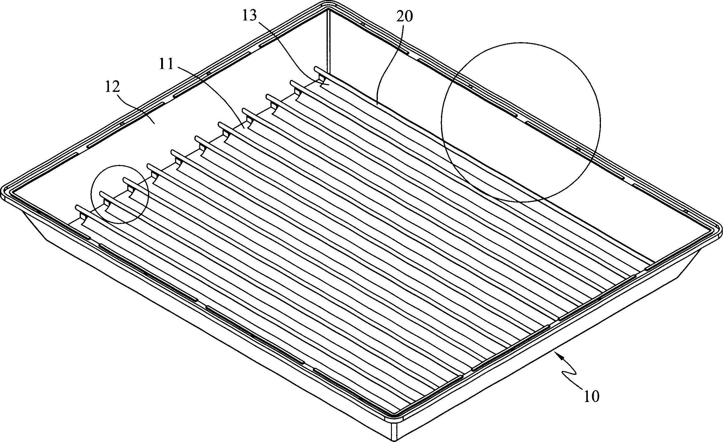
[0036] see figure 1 As shown, it is a backlight module heat dissipation design provided by the first preferred embodiment of the present invention, which is used to arrange behind a liquid crystal panel (not shown in the figure) to provide a uniform and high luminance backlight effect. The heat dissipation design of the backlight module includes:

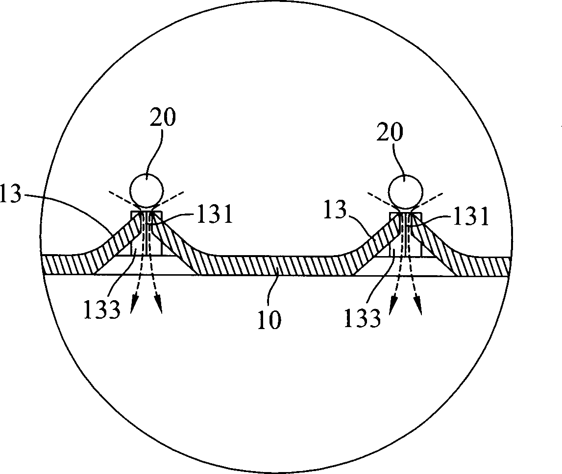
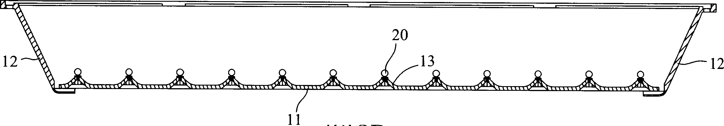
[0037] A base 10 is used to form a backlight module internal space, the base 10 has a reflective base plate 11 and a frame 12 surrounding the edge of the reflective base plate 11, the reflective base plate 11 and the frame 12 are located on one side of the backlight module internal space, Coated with reflective material to play a...


PUM


Abstract

The invention relates to a heat dissipation device for back light module, which comprises: placing plural parallel projections on a reflection base board, on the top of the projection having a first air through hole, and each top edge of the projection being able to position adjacent to tube light source; on the edge of the reflection board having plural second air through holes, a light shield is provided on the outside of the reflection bottom board for shielding each second air through holes; on the edge frame of the back light module having a flange which is provided with a slot for connecting to the inner space of the back light module, and on the bottom of the slot having a hole going through the flange to form a channel from inside of the back light module to outside; cooling air flow through the back light module is provided via the first, second and the third air through holes to prevent from forming shadow area.

Description

technical field [0001] The invention relates to a backlight structure of a liquid crystal display, in particular to a heat dissipation design of a backlight module that can improve the effect of the backlight. Background technique [0002] Liquid crystal display (LCD) is currently widely used in the production of various flat-panel displays. Compared with cathode tube displays, liquid crystal displays are more suitable for the production of large-scale displays. At this stage, color liquid crystal displays are based on liquid crystal thin film transistor liquid crystal displays (TFT -LCD), its basic structure is roughly divided into liquid crystal panel (LCD Panel), thin film transistor array substrate (TFT-LCD Substrate) and backlight module (backlight), the role of the backlight module is to emit visible light to penetrate the LCD panel A color change is formed for users to watch. [0003] The light source in the backlight module is provided by high luminance fluorescent ...

Claims


Application Information

Patent Timeline
Patent Type & Authority Applications(China)
IPC IPC(8): G02F1/1335G02F1/133
Inventor 林昆蔚卓英吉李金育洪基彬
Owner IND TECH RES INST
Why Eureka
Try Eureka