
Multipath rectification circuit

A rectifier circuit, AC voltage technology, applied in the direction of electrical components, high-efficiency power electronic conversion, irreversible AC power input conversion to DC power output, etc., can solve the problem of increased harmonic components, increased DC choke coil size, loss Increase and other problems, to achieve the effect of suppressing harmonic components

Inactive Publication Date: 2006-07-26
MITSUBISHI ELECTRIC CORP
View PDF2 Cites 5 Cited by
  • Summary
  • Abstract
  • Description
  • Claims
  • Application Information

AI Technical Summary

Problems solved by technology

[0010] However, in the above-mentioned conventional multi-channel rectification circuit, in principle, the purpose is to make the specific harmonic component zero, centering on the low-order harmonic of the input current. Increased problem when multiplexing measures are taken
[0011] In addition, in the above-mentioned existing multi-channel rectification circuit, in principle, due to the fact that the turns ratio of the multi-channel transformer selected in order to suppress low-order harmonics is very large for the DC choke coil that flows through the multiplexed DC , It is assumed that the DC current is a DC state without pulsation. Therefore, in order to achieve the effect, there is a problem that the size of the DC choke coil increases and the loss associated with it increases.

Method used


Image

  • Multipath rectification circuit
  • Multipath rectification circuit
  • Multipath rectification circuit

Examples


Embodiment Construction

[0054] The best embodiment of the multi-channel rectifier circuit according to the present invention will be described in detail below with reference to the accompanying drawings.

[0055] Embodiment 1

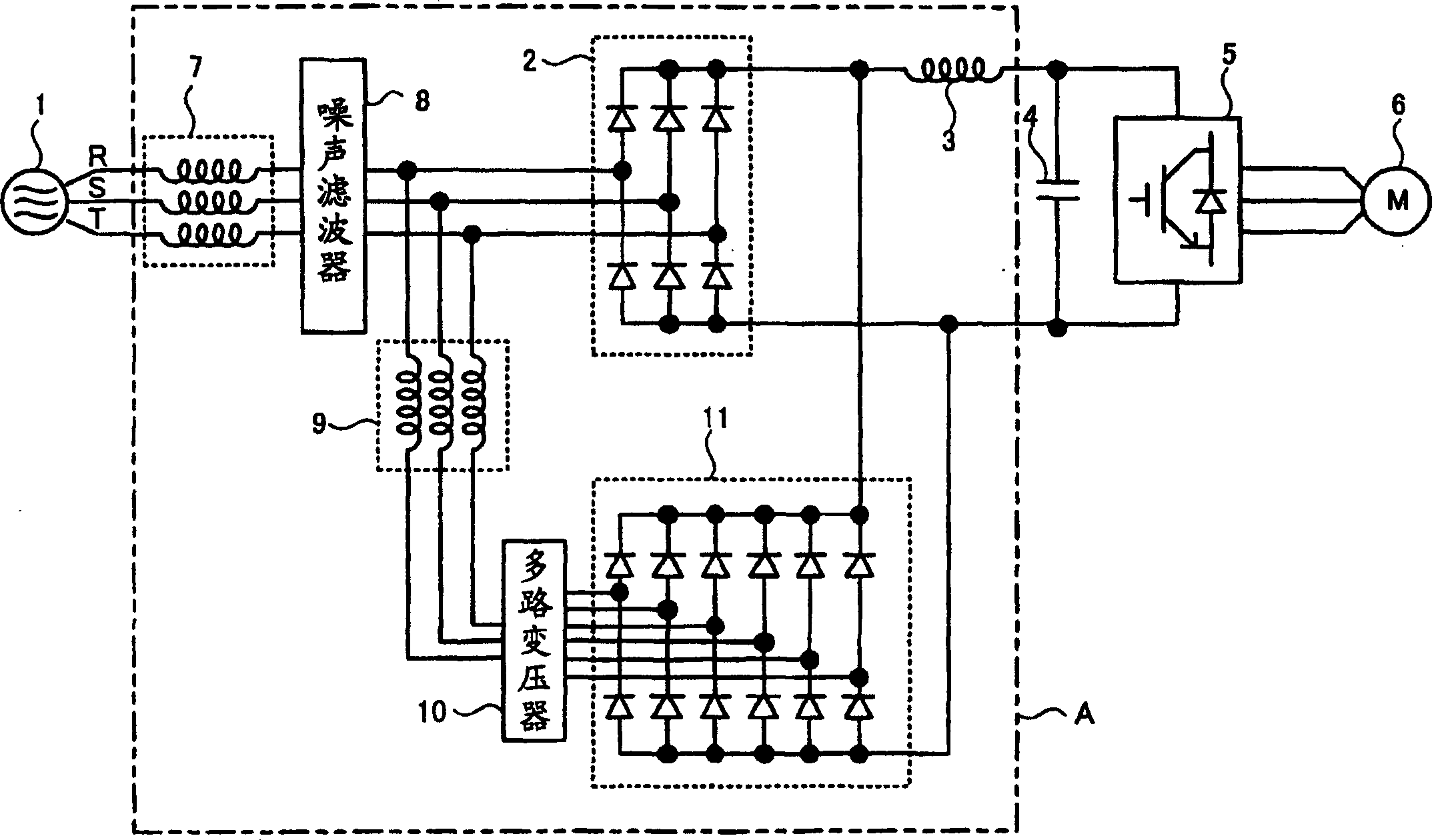
[0056] figure 1 It is a circuit diagram showing the configuration of a converter circuit using the multi-channel rectifier circuit according to Embodiment 1 of the present invention. figure 1 Among them, the converter circuit is generally composed of a first rectifier circuit 2 serving as a three-phase full-wave rectifier for the three-phase AC power supply 1, and a DC choke coil constituting a smoothing circuit for smoothing the output DC voltage of the first rectifier circuit 2. 3 and the smoothing capacitor 4, an inverter 5 that generates an AC voltage from the terminal voltage (DC voltage) of the smoothing capacitor 4, and drives and controls the motor 6 based on the output AC voltage of the inverter 5.

[0057] The multi-channel rectifier circuit (1) of the first embodime...


PUM


Abstract

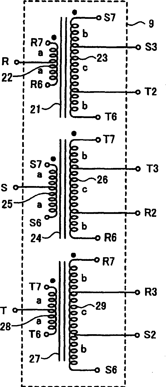
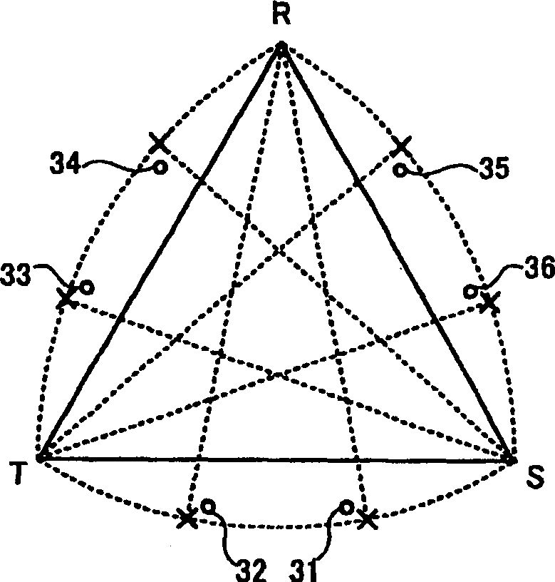
A multiplex transformer capable of not only suppressing low order harmonic components sufficiently but also suppressing all harmonic components with good balance while suppressing an increase in size of a DC reactor passing a multiplexed DC current. Since the turn ratio of the multiplex transformer (10) is selected to be one that can not only suppress harmonics of a specified order but also suppress all harmonics with good balance and AC reactors (9, 7) are inserted in order to suppress harmonics furthermore, all harmonic components can be suppressed with good balance in addition to sufficient suppression of low order harmonic components while suppressing an increase in size of the DC reactor (3) passing a multiplexed DC current, and not only national regulations but also European regulations can be dealt with.

Description

technical field [0001] The invention relates to a multi-channel rectification circuit for converting a three-phase AC power supply into a DC power supply with less harmonic components. Background technique [0002] As a method of converting three-phase AC to DC, the most common method is to use a three-phase full-wave rectifier in which six rectification elements are formed into a bridge structure. In the three-phase full-wave rectifier, since the rectifying elements that are energized sequentially every 60 degrees alternately switch the output DC voltage, the rectified DC voltage contains voltage fluctuations with 6 times the period of the power supply frequency and a large amplitude. This voltage pulsation becomes a harmonic wave and causes adverse effects on equipment using the DC power supply. [0003] For this reason, for example, in Patent Documents 1 and 2, it is proposed that for the first rectifier circuit that converts three-phase AC into DC, it is proposed to set...

Claims


Application Information

Patent Timeline
Patent Type & Authority Applications(China)
IPC IPC(8): H02M7/04
CPCY02B70/123H02M1/12H02M7/08H02M1/4266Y02B70/10H02M7/04
Inventor 高田茂生楠部真作
Owner MITSUBISHI ELECTRIC CORP
Learn More