Capacitive linear displacement sensor and movable ruler thereof
A linear displacement, capacitive technology, applied in the field of displacement sensors, can solve the problems of limiting the signal-to-noise ratio and accuracy of the sensor, low utilization of probe area, and small number of probe electrodes, so as to suppress harmonic components and enhance anti-interference. capacity, the effect of improving area utilization
- Summary
- Abstract
- Description
- Claims
- Application Information
AI Technical Summary
Problems solved by technology
Method used
Image
Examples
Embodiment 1
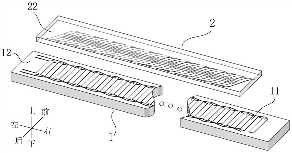
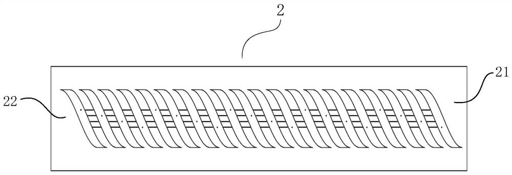
[0045] Embodiment 1: as Figure 1 to Figure 4 The capacitive linear displacement sensor shown includes a fixed scale 1 and a moving scale 2, the fixed scale 1 includes a moving scale base 12 and an excitation electrode 11 arranged on the upper surface of the fixed scale base 12, and the moving scale 2 includes a moving scale base 22 and a set The sensing electrode 21 on the lower surface of the moving scale base body 22 . The lower surface of the moving-scale base 22 is facing parallel to the upper surface of the fixed-scale base 12, leaving a gap of 0.5 mm. Both the fixed-scale base 12 and the moving-scale base 22 use ceramics as the base material, and a layer of ceramic is sprayed on the ceramic surface. The iron-nickel alloy is used as the pole piece of the electrode.
[0046] Such as figure 1 , figure 2 As shown, the excitation electrode 11 is composed of a row of rectangular pole pieces with the same size and a pole distance of W=2mm arranged at equal intervals along ...
Embodiment 2
[0050] Embodiment 2: as Figure 6 to Figure 8 The capacitive linear displacement sensor shown has the same measurement principle and most of its structures as in Embodiment 1, except that the shape of the sensing pole piece in the sensing electrode 21 is a parallelogram, and the parallelogram is composed of two identical oblique The line segment is surrounded by two straight line segments with a length of 1 mm at the start and end points. The distance between the starting points of two identical oblique line segments is 1 mm and the distance between the end points is 1 mm. Each oblique line segment is along the measurement direction. The length is 4mm, and the width along the front-back direction is 18mm, then the length of the sensing pole piece along the measurement direction is 5mm, and the width along the front-back direction is 18mm.
Embodiment 3
[0051] Embodiment 3: as Figure 9 to Figure 11 The capacitive linear displacement sensor shown has the same measurement principle and most of its structures as in Embodiment 1, except that the shape of the sensing pole piece in the sensing electrode 21 is a rectangle, and the length of the rectangle along the measuring direction is 1mm, along the The width in the front-rear direction is 18 mm.
PUM
 Abstract
Description
Claims
Application Information
 - R&D
- Intellectual Property
- Life Sciences
- Materials
- Tech Scout
- Unparalleled Data Quality
- Higher Quality Content
- 60% Fewer Hallucinations
Browse by: Latest US Patents, China's latest patents, Technical Efficacy Thesaurus, Application Domain, Technology Topic, Popular Technical Reports.
© 2025 PatSnap. All rights reserved.Legal|Privacy policy|Modern Slavery Act Transparency Statement|Sitemap|About US| Contact US: help@patsnap.com


