Method and device for grinding

A grinding and holding device technology, which is applied in the direction of grinding/polishing equipment, grinding machines, and machine tools designed for grinding the rotating surface of workpieces, etc., can solve the problems of long cycle and complicated control, so as to prolong life and avoid long cycle Life-enhancing effect

Active Publication Date: 2006-08-02
KOYO MASCH IND CO LTD
View PDF1 Cites 5 Cited by
  • Summary
  • Abstract
  • Description
  • Claims
  • Application Information

AI Technical Summary

Problems solved by technology

[0007] However, in the grinding method disclosed in the aforementioned Japanese Patent No. 2001-47344, since the relative reciprocation between the piston W and the grinding wheel may not be completed even when the rotation of the piston W is completed, there is a problem of a long cycle time.
Moreover, in order to prevent such a problem, it is sufficient to synchronize the relative reciprocating movement of the piston W and the grinding wheel with the rotation of the piston W, but in order to achieve synchronization, the control of these actions becomes complicated.

Method used


Image

  • Method and device for grinding
  • Method and device for grinding
  • Method and device for grinding

Examples


Embodiment Construction

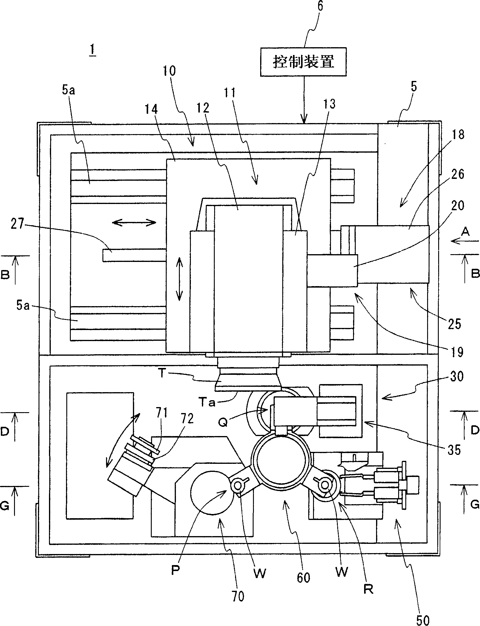
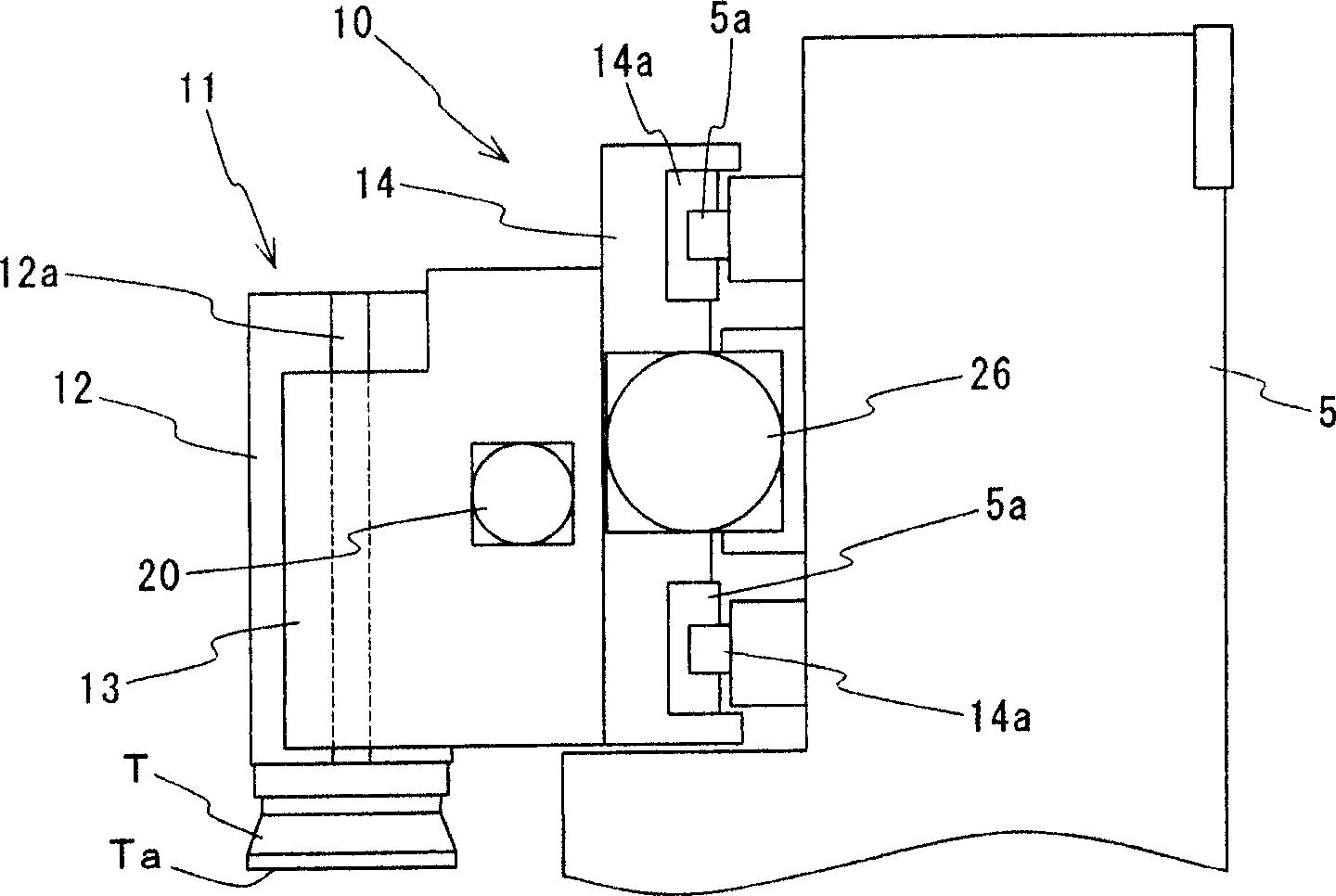
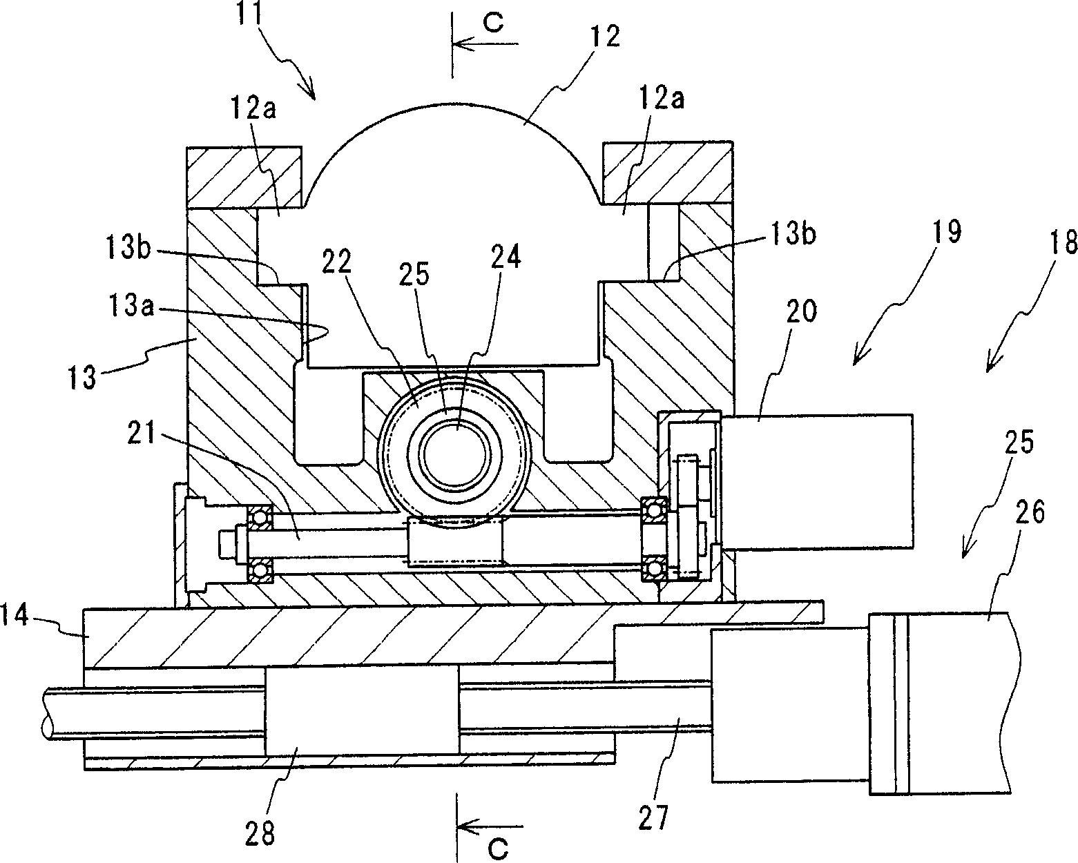
[0069] Hereinafter, embodiments of the present invention will be described in detail with reference to the drawings. in, figure 1 It is a plan view showing a schematic structure of a grinding device in one embodiment of the present invention, figure 2 is along figure 1 A side view in the direction of the arrow A, image 3 is along figure 1 The cross-sectional view of the arrow B-B direction, Figure 4 is along image 3 The cross-sectional view of the arrow C-C direction, Figure 5 is along figure 1 The cross-sectional view of the arrow D-D direction, Figure 6 is along Figure 5 A side view in the direction of the arrow E, Figure 7 is along Figure 6 A side view in the direction of arrow F. and, Figure 8 is along figure 1 The cross-sectional view of the arrow G-G direction, Figure 9 is a plan view showing a schematic configuration of the supply unit in the embodiment, Figure 10 is along Figure 9 The cross-sectional view of the arrow H-H direction.

...


PUM


Abstract

The present invention provides a grinding method capable of preventing abrasion of only a part of a grinding action surface of a cup-shaped grinding wheel, by changing a contact position of the cup-shaped grinding wheel and a work. The cup-shaped grinding wheel T having the annular grinding action surface and the cylindrical work W are respectively arranged so that these axes are mutually orthogonal, and the cup-shaped grinding wheel T and the work W are rotated around the axis. An outer peripheral surface of the work W is ground by contacting the grinding action surface with the outer peripheral surface of the work W. Every time when rotating the work W by a preset frequency in a state of contacting the grinding action surface of the cup-shaped grinding wheel T with the outer peripheral surface of the work W, the cup-shaped grinding wheel T and the work W are relatively moved in the direction orthogonal to both the axis of the cup-shaped grinding wheel T and the axis of the work W, to change a position for contacting the grinding action surface with the outer peripheral surface of the work W.

Description

technical field [0001] The present invention relates to a grinding method and a grinding device for grinding the outer peripheral surface of a workpiece processed into a cylindrical shape by using the grinding action surface of a cup-shaped grinding wheel having an annular grinding action surface. Background technique [0002] As an example of a cylindrical workpiece, for example, such as Figure 13 As shown, a piston W provided in a rotary compressor to compress a predetermined fluid includes vanes (protrusions) Wa formed on the outer peripheral surface and through-holes Wb opened on both end surfaces. in addition, Figure 13 (a) A plan view showing an example of a workpiece, Figure 13 (b) is along Figure 13 (a) Side view in the direction of the arrow. [0003] For the processing of the outer peripheral surface of the piston W, in the prior art, the cup-shaped grinding wheel and the piston W having an annular grinding action surface are respectively arranged so that their...

Claims


Application Information

Patent Timeline
Patent Type & Authority Applications(China)
IPC IPC(8): B24B5/00
Inventor 西口正巳平冈贵树
Owner KOYO MASCH IND CO LTD
Why Eureka
Try Eureka