Ultrasonic bonding equipment and resulting bonding structure

A joining device and ultrasonic technology, applied in the direction of welding/welding/cutting items, manufacturing tools, structural parts, etc., can solve the problems of cracks, easy cracks, stress concentration, etc., to prevent cracks, prevent fractures, The effect of alleviating stress concentration

Active Publication Date: 2006-08-09
ENVISION AESC JAPAN LTD
View PDF3 Cites 22 Cited by
  • Summary
  • Abstract
  • Description
  • Claims
  • Application Information

AI Technical Summary

Problems solved by technology

Therefore, the junction point between the grip area and the non-grip area expands and contracts the most during vibration, so cracks are likely to occur
In addition, after the metal plates are joined, stress concentration due to external force tends to occur at the part where the thickness of the outer part of the joined part becomes thinner, and this becomes a cause of cracks.

Method used


Image

  • Ultrasonic bonding equipment and resulting bonding structure
  • Ultrasonic bonding equipment and resulting bonding structure
  • Ultrasonic bonding equipment and resulting bonding structure

Examples


Embodiment Construction

[0045] Hereinafter, embodiments of the present invention will be described in detail with reference to the drawings.

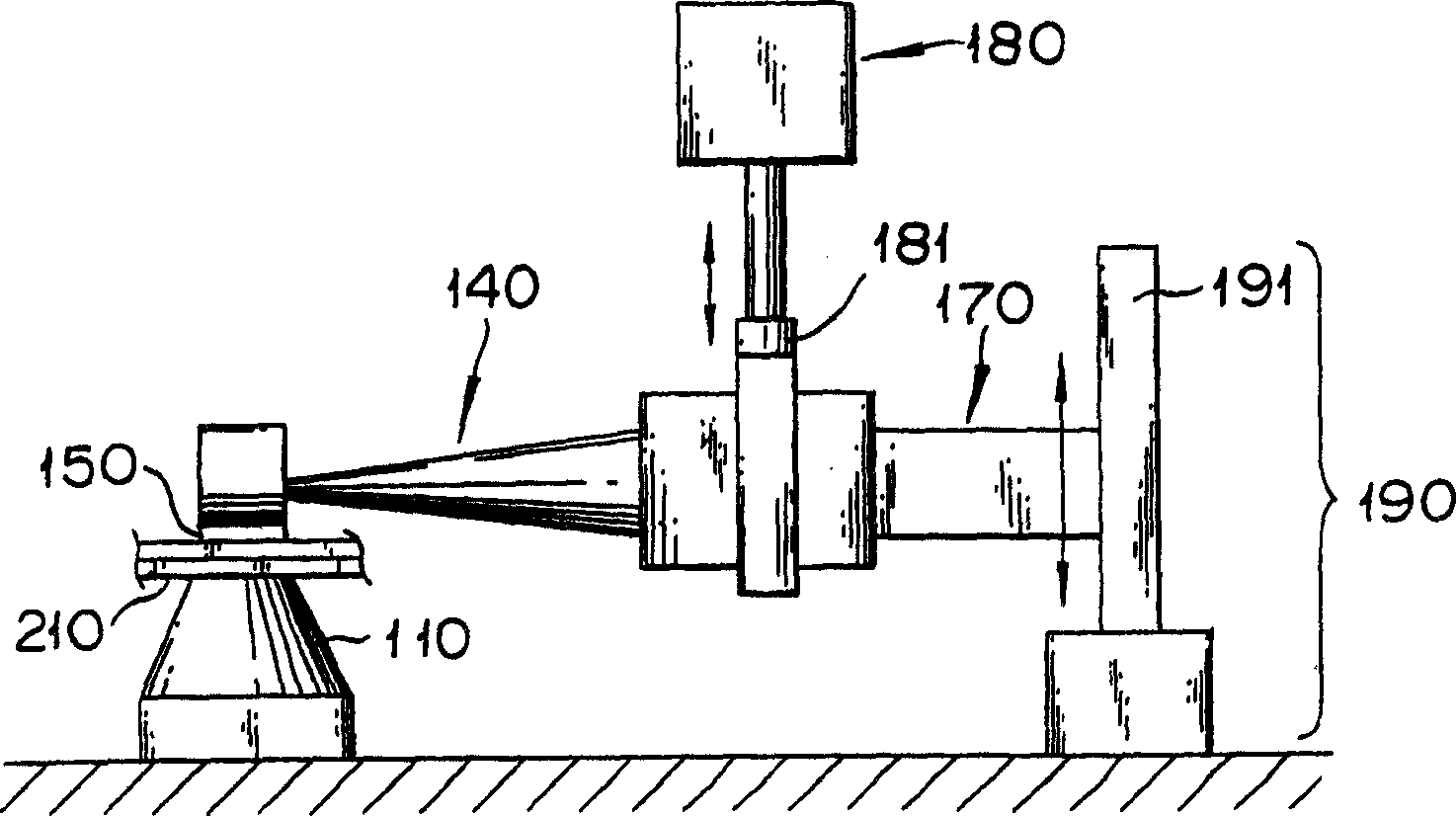
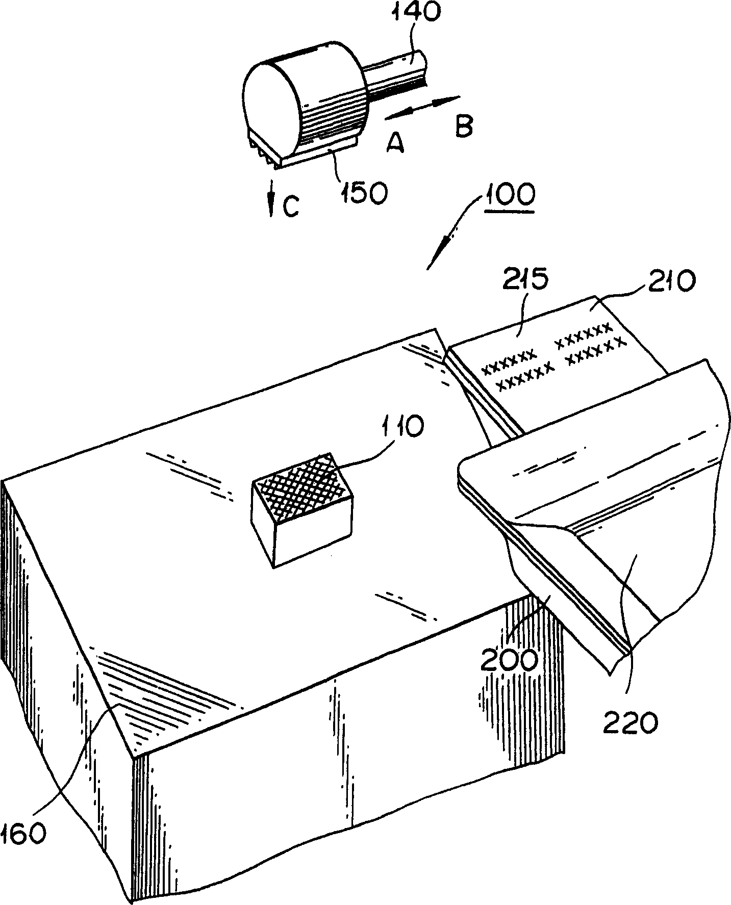
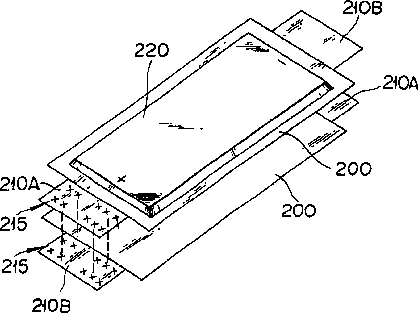
[0046] figure 1 is a schematic configuration diagram of an ultrasonic bonding apparatus according to an embodiment of the present invention. figure 2 It is a partial schematic perspective view of the ultrasonic bonding apparatus of this embodiment. image 3 It is a schematic structural diagram of a flat cell as a bonded object. Figure 4 It is a figure which shows the state which joined the electrode tab of a single cell by the ultrasonic joining apparatus of this embodiment.

[0047] Such as figure 1 with figure 2 As shown, the ultrasonic bonding apparatus 100 has an anvil 110 , a horn 140 , an ultrasonic vibrator 170 , and a pressing device 180 . The anvil 110 is a fixed-side tool that receives ultrasonic vibrations in the ultrasonic bonding apparatus 100 . The horn 140 is a member that transmits the ultrasonic vibration generated by the ultrasonic v...


PUM


Abstract

The invention provides an ultrasonic bonding equipment and a bonding construction body to increase the strength of a joined part of a work after the ultrasonic bonding is completed. An ultrasonic bonding equipment has an anvil 110 and a horn 140 arranged facing the anvil, and performs the ultrasonic bonding of the work to be bonded by pressurizing and oscillating electrode tabs 210 as a plurality of works overlapped and set on the anvil by the horn. Gripping force on the outer side part is set to be smaller than the gripping force on the inner side part in a gripping area to the works by the anvil and the horn.

Description

technical field [0001] The present invention relates to an ultrasonic bonding device and a bonded structure obtained by ultrasonic bonding a plurality of laminated objects to be bonded. The ultrasonic bonding device includes an anvil and a horn disposed opposite to the anvil. Background technique [0002] The ultrasonic bonding device uses an anvil with a protrusion on the surface and a bonding tool called a horn to sandwich, for example, two overlapping metal plates (of the same type or different types) and apply a predetermined pressure (holding force) to them. At the same time, the horns are reciprocated and linearly moved by ultrasonic vibration to join these metal plates (Japanese Patent Application Laid-Open No. 9-239567 and Japanese Patent Laid-Open No. 10-225779). [0003] When the ultrasonic bonding device is in use, impurities such as oxide films are removed by rubbing the contact surfaces of two metal plates, and the clean surfaces of the metals are brought into c...

Claims


Application Information

Patent Timeline
Patent Type & Authority Applications(China)
IPC IPC(8): B23K20/10H01M4/00B23K101/36
CPCB29C66/81433B29C65/081B29C66/1122B29C66/21B29C66/43B29C66/81435B29C66/8322B29L2031/3468
Inventor 清水明松山秀信
Owner ENVISION AESC JAPAN LTD
Why Eureka
Try Eureka