
Tendon running-water quenching method and apparatus

A technology of quenching device and steel bundle, which is applied in the direction of quenching device, furnace, heat treatment equipment, etc., can solve the problems of inability to further obtain the performance of steel bars, difficult control and adjustment of process parameters, etc., and achieve the effect of improving the strength and stability of turning threads.

Inactive Publication Date: 2006-08-09
SHANGHAI ZHUGUANG MACHINERY +1
View PDF0 Cites 6 Cited by
  • Summary
  • Abstract
  • Description
  • Claims
  • Application Information

AI Technical Summary

Problems solved by technology

However, according to the cold water quenching treatment carried out on the surface of steel bars used in construction, engineering, etc. in the past, the steel bars are continuously showered with flowing water, or only when the steel bars are rolled off, the steel bars are flushed and quenched. Therefore, it is difficult to further control and adjust the various process parameters in the quenching process, so that it is impossible to further obtain different steel properties

Method used


Image

  • Tendon running-water quenching method and apparatus
  • Tendon running-water quenching method and apparatus
  • Tendon running-water quenching method and apparatus

Examples


Embodiment 1

[0046] In this embodiment, beam water quenching is performed on threaded steel bars used in construction and engineering.

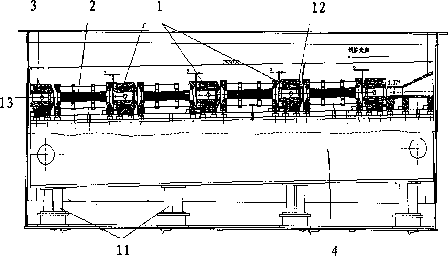
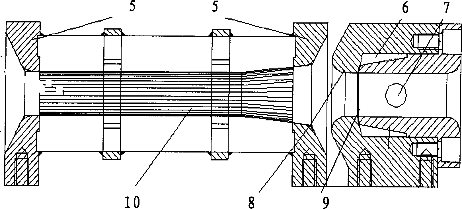
[0047] like figure 1 As shown, in the beam water quenching method and device, 4 beam water quenching section components 1 and 4 squirrel-cage drainage section components 2 constitute a steel beam water quenching channel, such as figure 1 As shown, the threaded steel bar 12 used in construction, engineering, etc. runs from right to left, and enters the first reinforcement beam water quenching section member from the trumpet-shaped port 8 of the beam water quenching section member 1. The component 1 for the quenching section of steel tendons and the multiple squirrel-cage drainage section components 2 are spaced apart from each other. The length of the first beam water quenching section is 0.6-0.8m, the length of the second beam water quenching section is 0.6-0.8m, the third beam water quenching section is 0.4-0.6m, and the fourth beam water quenching sect...

Embodiment 2

[0062] Except that two compressed air nozzles are arranged at the end of the beam flow channel, the water spray holes on the beam water quenching section components are arranged in two rows in an annular shape, and the water spray holes on the beam water quenching section components have an aperture diameter of 3 Except -5mm, other is the same as embodiment 1, constitutes the beam water quenching device of the threaded steel bar that construction, engineering etc. use.

Embodiment 3

[0064] Except that the temperature of the steel bar at which the steel bar starts to enter the first beam water quenching working section is 1200-1400°C, and the passing speed of the steel bar in the beam water quenching channel is 2-6m / s, the others are the same as in embodiment 1, It is a beam water quenching device for threaded steel bars used in construction and engineering.


PUM


Abstract

This invention relates to a water-quenching method and a device for steel bars, in which, the method includes: high temperature steel bars pass through a water-quenching channel composed of multiple water-quenching section components and multiple rotor-cage-like drainage section components set in gaps while water flows through the multiple stream nozzles on the components of the water-quenching section to rush to the bars at high speed in the tilted angle inverted to the movement of the bars to force them to reduce the temperature quickly then to enter into the cage-state drainage components orderly after the oxidized slags on the surface are washed out and said stream water-quenching is carried out for many times, finaly, the bar enters into the compressed air jet section component at the end of the lower reaches of the channel, which stops water flowing along the steel bar , which is blown at the outlet .

Description

technical field [0001] The invention relates to a method and device for quenching steel bars, more specifically, the invention relates to a beam water quenching method and device for steel bars used in construction and engineering. Background technique [0002] In order to meet the requirements for high strength, surface corrosion resistance and surface rigidity of steel bars, etc., usually, after the hot-rolled manufacturing of steel bar profiles for construction, engineering, etc., the surface of the steel bar needs to be adjusted. Cold water quenching treatment is carried out, thereby obtaining the requirements for the technical performance of steel bars used in construction, engineering, etc., such as inherent high strength, surface corrosion resistance, and surface rigidity. For example, in the past one or two decades, so-called "water-hardened steel bars" have been widely used as steel bars for construction, engineering, etc. [0003] "Water-quenched steel bar" also u...

Claims


Application Information

Patent Timeline
IPC IPC(8): C21D9/56C21D1/667C21D11/00
Inventor 吴俊金文达
Owner SHANGHAI ZHUGUANG MACHINERY
Learn More