Vapor deposition source and vapor deposition apparatus having the same

An evaporation source and evaporation technology, which is applied in the direction of vacuum evaporation coating, coin-operated equipment for distributing discrete items, sputtering coating, etc., can solve the problems of increasing the evaporation source and the installation cost of heat insulation materials, etc. To achieve the effect of improving quality

Active Publication Date: 2006-08-09
SAMSUNG DISPLAY CO LTD
View PDF0 Cites 55 Cited by
  • Summary
  • Abstract
  • Description
  • Claims
  • Application Information

AI Technical Summary

Problems solved by technology

[0008] Therefore, the volume of the vapor deposition source must be increased, and the installation cost of the heat insulating material installed on such a large vapor deposition source is increased. In addition, the transfer device for moving the vapor deposition source is also required to have a high power.

Method used


Image

  • Vapor deposition source and vapor deposition apparatus having the same
  • Vapor deposition source and vapor deposition apparatus having the same
  • Vapor deposition source and vapor deposition apparatus having the same

Examples


Embodiment Construction

[0037] Hereinafter, the evaporation source and the evaporation apparatus using the evaporation source of the present invention will be described in detail with reference to the drawings.

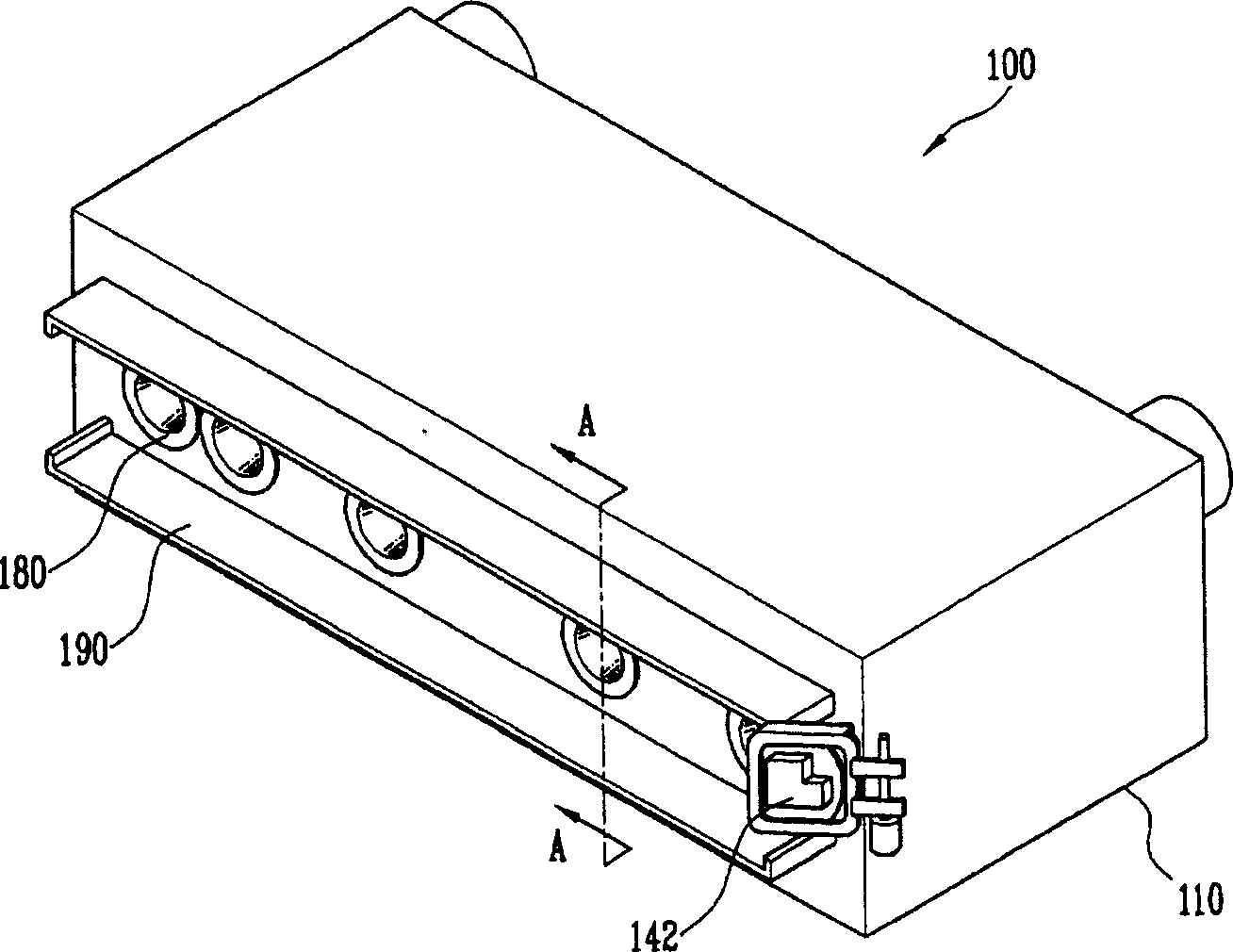
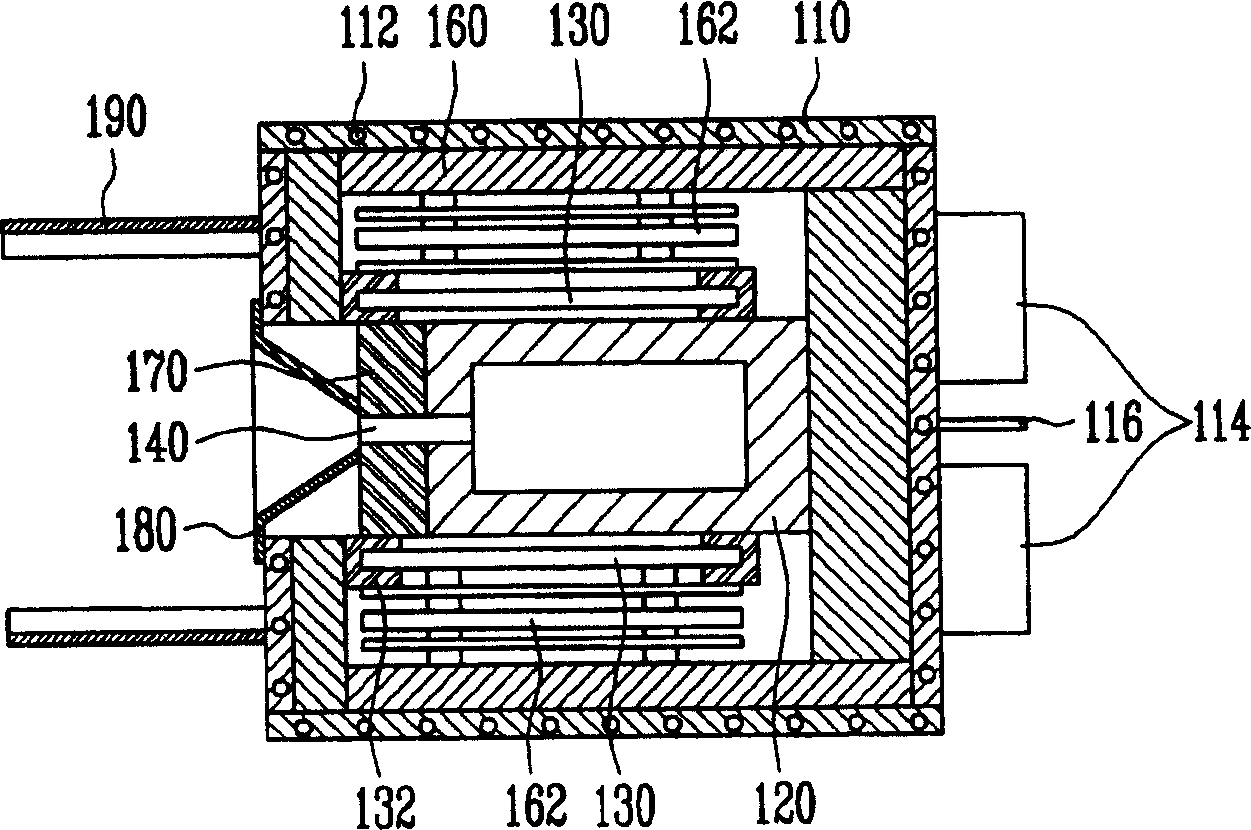
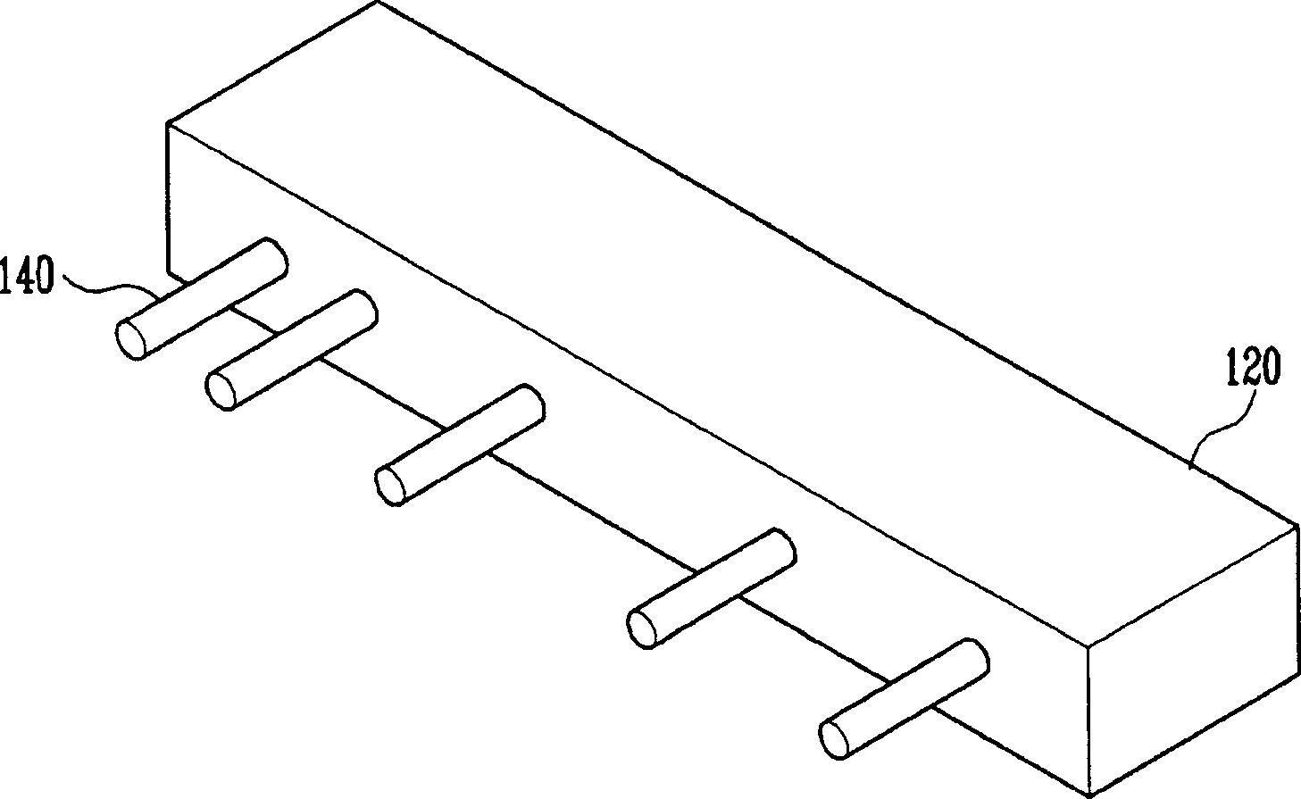
[0038] figure 1 It is a perspective view schematically showing an evaporation source of an ideal embodiment of the present invention; figure 2 is along figure 1 Sectional view of line A-A. Referring to the accompanying drawings, the evaporation source 100 of the present invention includes a crucible 120 disposed inside the housing 110, a heating portion having a heater 130 for heating the crucible 120, a heat insulating material having a plurality of heat insulating materials covering the heating portion. part and a nozzle part communicating with the crucible 120 and having a spray nozzle 140 for spraying the vapor deposition material to the outside.

[0039] The crucible 120 accommodates vapor deposition substances, and in order to heat the crucible 120, a heater 130 is arranged around ...


PUM

PropertyMeasurementUnit
diameteraaaaaaaaaa

Abstract

The invention provides a vaporization source, wherein a crucible, a heating portion and a nozzle portion are arranged in one partitioned space so as to reduce the size, and a vapor deposition apparatus for depositing deposition materials on a substrate using the vaporization source. The apparatus includes a housing 100, a crucible 120 built in the housing 110, a heating portion which is positioned around the crucible 12 built in the housing 110 in order to heat the crucible 12, and a nozzle portion injecting the deposition materials vaporized from the crucible 120 into a substrate 220 disposed at an exterior of the housing 110 through an injection nozzle 140.

Description

technical field [0001] The present invention relates to an evaporation source and an evaporation device using the evaporation source. More specifically, it relates to an evaporation source in which a crucible and a nozzle portion are housed in a housing, and an evaporation device equipped with the evaporation source. Background technique [0002] Generally, evaporation devices are used for thin film deposition of various electronic components, and are mainly used in thin film formation of electronic devices such as semiconductors, LCDs, and organic electric field display devices, and display devices. [0003] The organic electroluminescent display device respectively injects electrons and holes into the light-emitting layer from the electron injection electrode and the hole injection electrode, and the excitons combined with the injected electrons and holes fall back from the excited state to the base Lights up when in state. [0004] Here, in order to improve the luminous ...

Claims


Application Information

Patent Timeline
Patent Type & Authority Applications(China)
IPC IPC(8): C23C14/26
CPCA63F13/90A63F2250/14G07F17/32
Inventor 金度根许明洙郑锡宪康熙哲古野和雄
Owner SAMSUNG DISPLAY CO LTD
Why Eureka
Try Eureka