Slip-sheet for rotary compressor

A technology of rotary compressors and sliding vanes, which is applied in the direction of rotary piston machines, rotary piston pumps, rotary piston/swing piston pump components, etc., which can solve the problem of affecting the reliability of compressors and increasing mechanical friction power Loss, reduce compressor and other issues, to achieve the effect of reducing mechanical friction power loss, improving the COP of the compressor, and reducing friction power

Inactive Publication Date: 2006-08-09
李玉斌
View PDF0 Cites 10 Cited by
  • Summary
  • Abstract
  • Description
  • Claims
  • Application Information

AI Technical Summary

Problems solved by technology

Therefore, the slider 3 interacts with the cylinder slider groove 4, and the outer side of the slider has forces F1 and F2 respectively on the suction side of the lower part of the cylinder slider groove and the upper exhaust side of the cylinder slider groove. These two forces cause The friction and wear on the side of the sliding plate 3, especially the sliding plate groove 4, not only affects the reliability of the compressor, but also increases the loss of mechanical friction power and reduces the COP of the compressor.

Method used


Image

  • Slip-sheet for rotary compressor
  • Slip-sheet for rotary compressor
  • Slip-sheet for rotary compressor

Examples


Embodiment 1

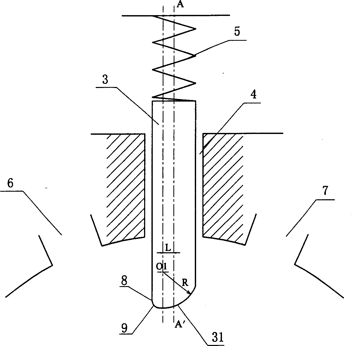
[0029] image 3 Shown is one of the embodiments of the present invention, the bottom end surface 31 of the slide piece 3 is arc-shaped, the center O1 of the arc shape is biased towards the exhaust port 6, the bottom end of the bottom end surface 31 of the slide piece is in line with the outside of the slide piece The inflection points 8 are transitioned by a smooth arc 9, so as to raise the position of the inflection point at the bottom of the sliding plate, avoid contact with the piston, and reduce the friction and wear between the sliding plate and the piston. The distance L between the center of circle O1 and the vertical center line AA' of the slider is 1 / 8 to 1 / 3 times of the width of the slider, preferably 1 / 4 of the width of the slider. The bottom end surface 31 of the slider is in the shape of a continuous arc and intersects with the edges on both sides of the slider 3. The radius R is 0.6-2 times the width of the slider, preferably 1.58 times the width of the slider. ...

Embodiment 2

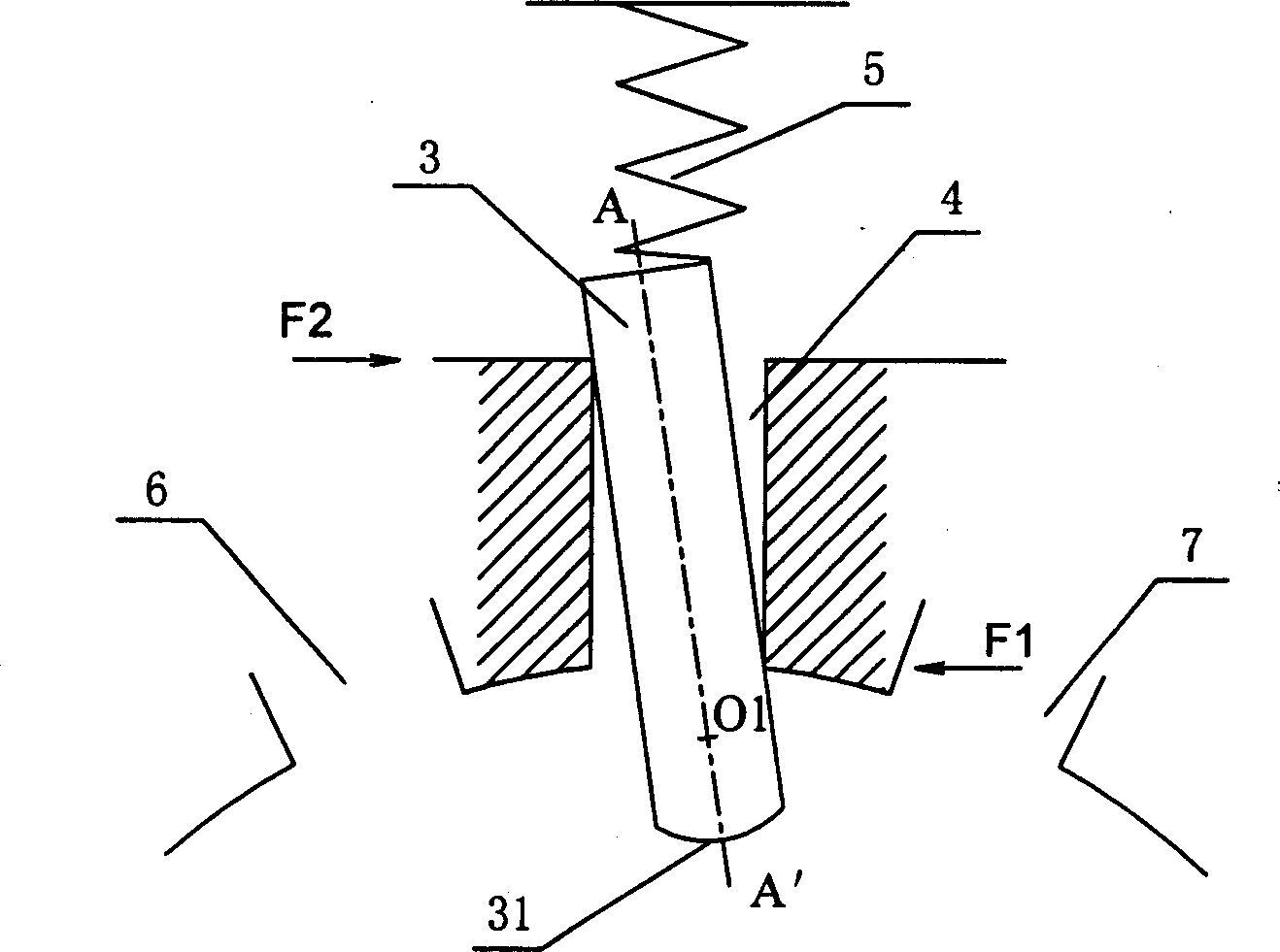
[0039] Figure 4 Shown is the second embodiment of the present invention, which is different from the first embodiment in that: due to the processing of grinding tools or cutters, the radius of curvature R of the arc-line end surface 31 at the bottom of the slide plate may be smaller than the center of curvature O1 to the slide plate The vertical distance from the edge of the suction side, that is, the end surface 31 of the arc line at the bottom of the slide will not directly intersect with the edge of the suction side of the slide, and there is a connecting end surface 32 between the two, so the bottom of the slide presents a combined form , but the object of the present invention can also be achieved. The connection end surface 32 can be a straight line or a curved line, which is completely determined by the shape of the grinding tool or cutter for processing the bottom curve of the slide plate, and does not affect the implementation of this embodiment. The distance L betw...


PUM


Abstract

Present invention discloses a slide piece for rotary compressor. Said end surface end surface contour is smooth curve, the curvature centre of said curve deviated to air outlet, the end surface of slide piece bottom being not symmetric along slide piece center line, but one side corresponded air suction port being higher than one side corresponded air outlet. When compressor is in operation, said asymmetrical shape can relieve slide piece tilted position, thereby reducing frictional wear and mechanical friction power loss between slide piece and slide piece trough, reducing slide piece blocking duo to assembly deformation, raising compressor reliability and COP.

Description

technical field [0001] The present invention relates to a component of a rotary compressor, in particular to a sliding vane for a rotary compressor. Background technique [0002] The scientific name of the rotary compressor is the rolling piston compressor, which is widely used in the field of household air-conditioning compressors and occupies an absolute majority of the market share. Therefore, in this field, the rotary compressor refers to the rolling piston compressor. [0003] How rotary compressors work see figure 1 , the piston 1 is set eccentrically in the cylinder 2, that is, the circle center O' of the piston 1 must have a certain deviation from the circle center O of the cylinder 2, so that the inner wall of the cylinder 2 and the outer wall of the piston 1 form a crescent-shaped cavity. The slide plate 3 is installed in the slide plate groove 4 of the cylinder, and the upper end of the slide plate 3 is driven by the slide plate spring 5, and extends into the cy...

Claims


Application Information

Patent Timeline
Patent Type & Authority Applications(China)
IPC IPC(8): F04C29/00F04C18/356
Inventor 李玉斌
Owner 李玉斌
Why Eureka
Try Eureka