[0007] 1. Since the design of the probe set 50 is extremely small, when the inner sleeve 502 itself is already extremely small, the elastic element 503 and the probe 504 which are movable and arranged on the inner sleeve 502 will be even smaller , so, not only is it extremely expensive and uneconomical in terms of manufacturing costs, especially, it also has the disadvantages of troublesome, inconvenient and uneconomical with a very high technical level in
assembly.
[0008] 2. Since the elastic element 503 placed in the inner sleeve 502 is extremely small, its service life must not be long, and once the elastic element 503 is damaged, it will directly affect the test results. In this way, the operator must replace the probe set 50 regularly Under the circumstances, there are obviously more troublesome, inconvenient and uneconomical phenomena in implementation
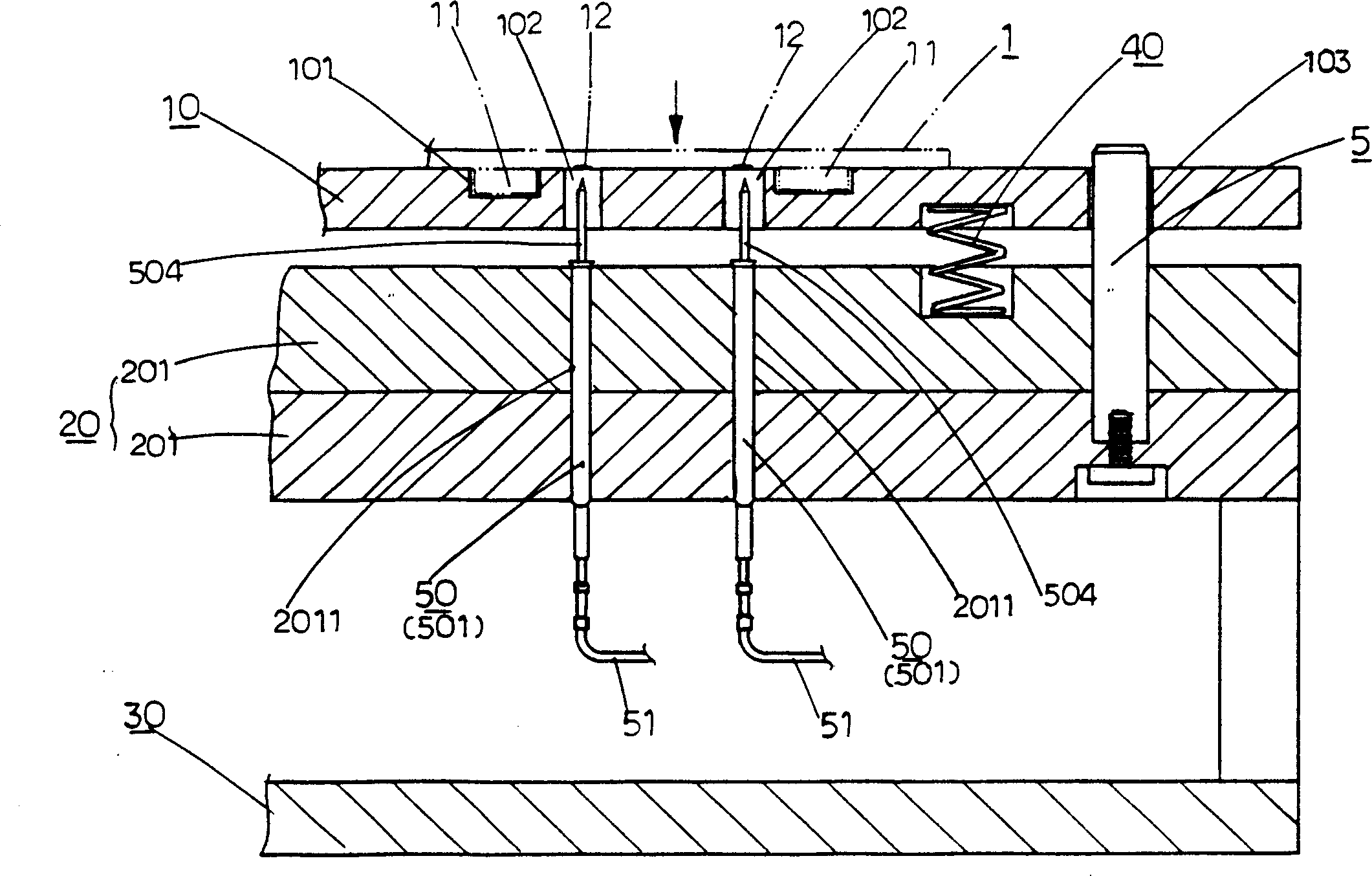
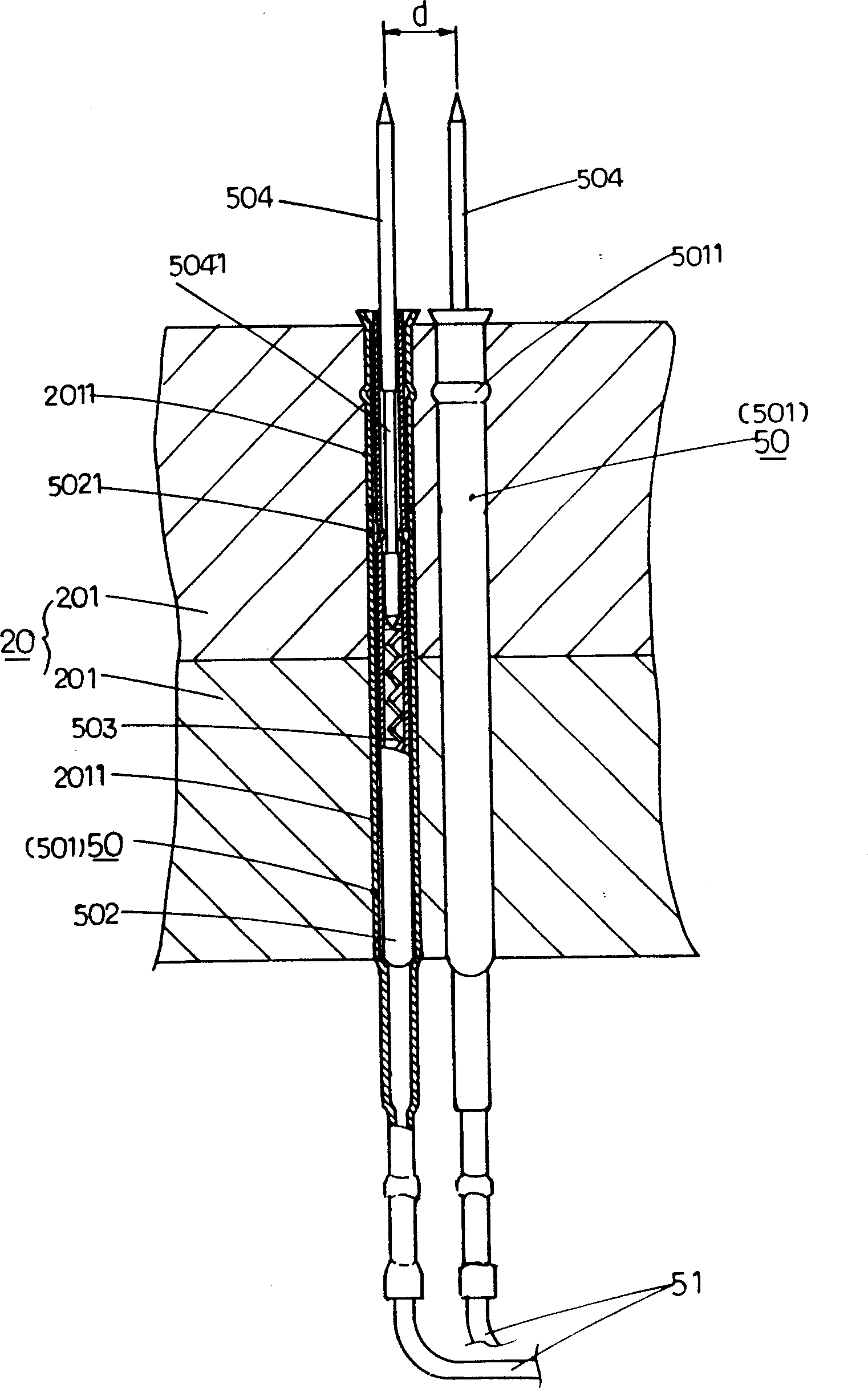
[0009] 3. Since the outer sleeves 501 of the probe sets 50 are vertically inserted into the splint 201 fixed on the wire tray 20, the inner sleeves 502 and probes 504 are also vertical. In such a situation, it is inevitable that the
minimum distance d between the centers of the probes 504 (as shown in the second figure) will only reach the state where the two outer sleeves 501 are adjacent, and cannot be further reduced (currently this The probe of the
type test fixture can detect the
minimum distance between the points to be measured is about 1.0mm or more), so, in view of the fact that the density of the points to be measured is getting smaller and smaller, it is a kind of fixture and probe The structure obviously has the
disadvantage that it is not enough for practical needs.
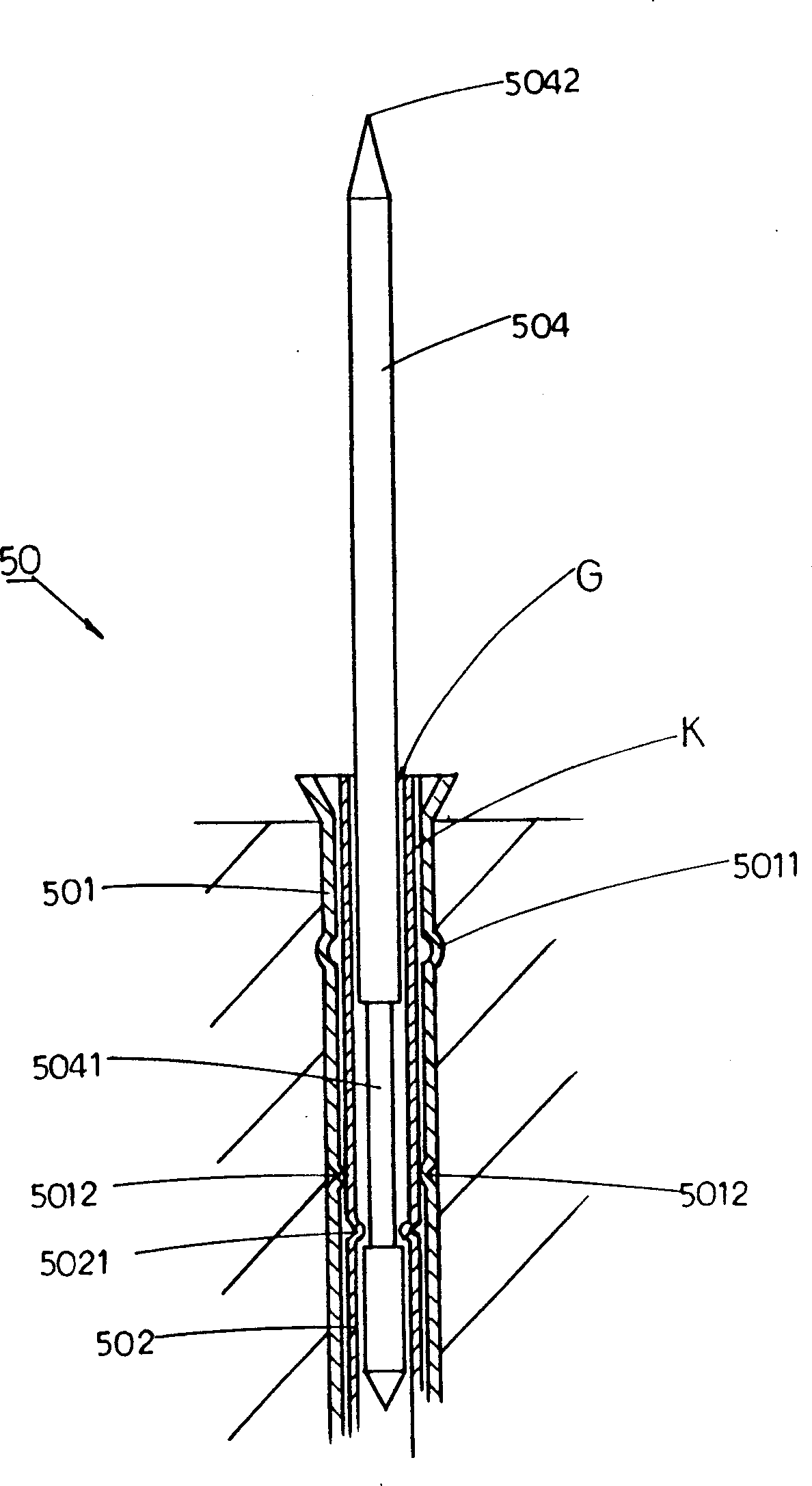
[0010] 4. Since the probe 504 is loosely fitted behind the inner sleeve 502, the inner
flange 5021 of the inner sleeve 502 is positioned against falling off, and the inner sleeve 502 is fitted behind the outer sleeve 501. The two concave points 5012 of the outer sleeve 501 are properly clamped, so there are movable gaps between the probe 504 and the inner sleeve 502, and between the inner sleeve 502 and the outer sleeve 501. Under the circumstances of G and K, it is inevitable that the action of the elastic lifting of the probe 504 will not be constant in a
vertical straight line, but free shaking will occur. In particular, the probe 504 has a certain length and is exposed. Because of the inner sleeve 502, it will inevitably cause its head end 5042 to generate a larger shaking and swing range. In this way, when the probe head end 5042 touches the position of the
test point 12 of the mounting board 1 to be tested, it will Unstable, inaccurate, inaccurate, or even inaccessible situations will occur, and this will greatly reduce the effect of the detection of the mounted board
[0011] 5. After the probe group 50 is assembled on the reel 20, the floating plate 10 performs the
assembly action, and the detection probes 504 are hundreds in number except that they are extremely thin. Each through-hole 102 of the floating plate 10 can smoothly pass through the probe 504, and the aperture of these through-holes 102 must be much larger than the
diameter of the probe 504. In the situation where the head end of the swinging and shaking probe 504 mentioned in the preceding item provides support and guidance, it is obvious that the floating plate 10 can only serve as a bearing for the object to be measured, but cannot improve the stability of the probe detection at all. , precision and certainty
In order to solve the problems existing in the test method of the mounted board, the relevant manufacturers have tried their best to find a solution, but no suitable design has been developed for a long time, and there is no suitable test method for the general mounted board. The method can solve the above problems, which is obviously a problem that the relevant industry is eager to solve

