Electric driving apparatus for bicycle

An electric drive, bicycle technology, applied in the direction of electromechanical devices, transmission devices, bicycle accessories, etc., can solve the problems of worm lock, worm tooth wear and so on.

Inactive Publication Date: 2006-08-16
SHIMANO INC
View PDF1 Cites 17 Cited by
  • Summary
  • Abstract
  • Description
  • Claims
  • Application Information

AI Technical Summary

Problems solved by technology

If the output shaft of the motor is deflected in the direction away from the worm wheel as described above, problems such as locking of the worm or wear of the worm teeth may occur.

Method used


Image

  • Electric driving apparatus for bicycle
  • Electric driving apparatus for bicycle
  • Electric driving apparatus for bicycle

Examples


other Embodiment approach

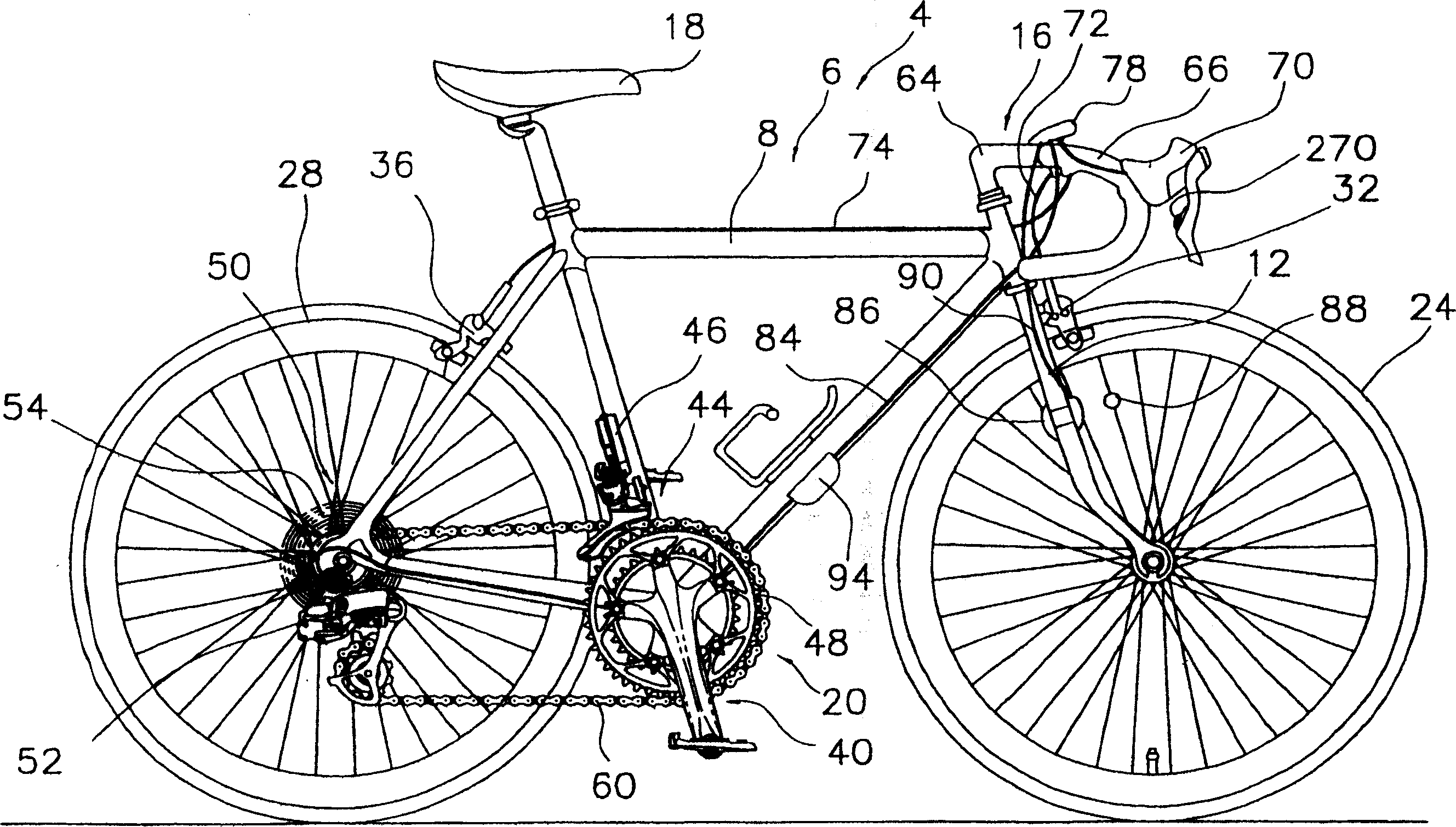
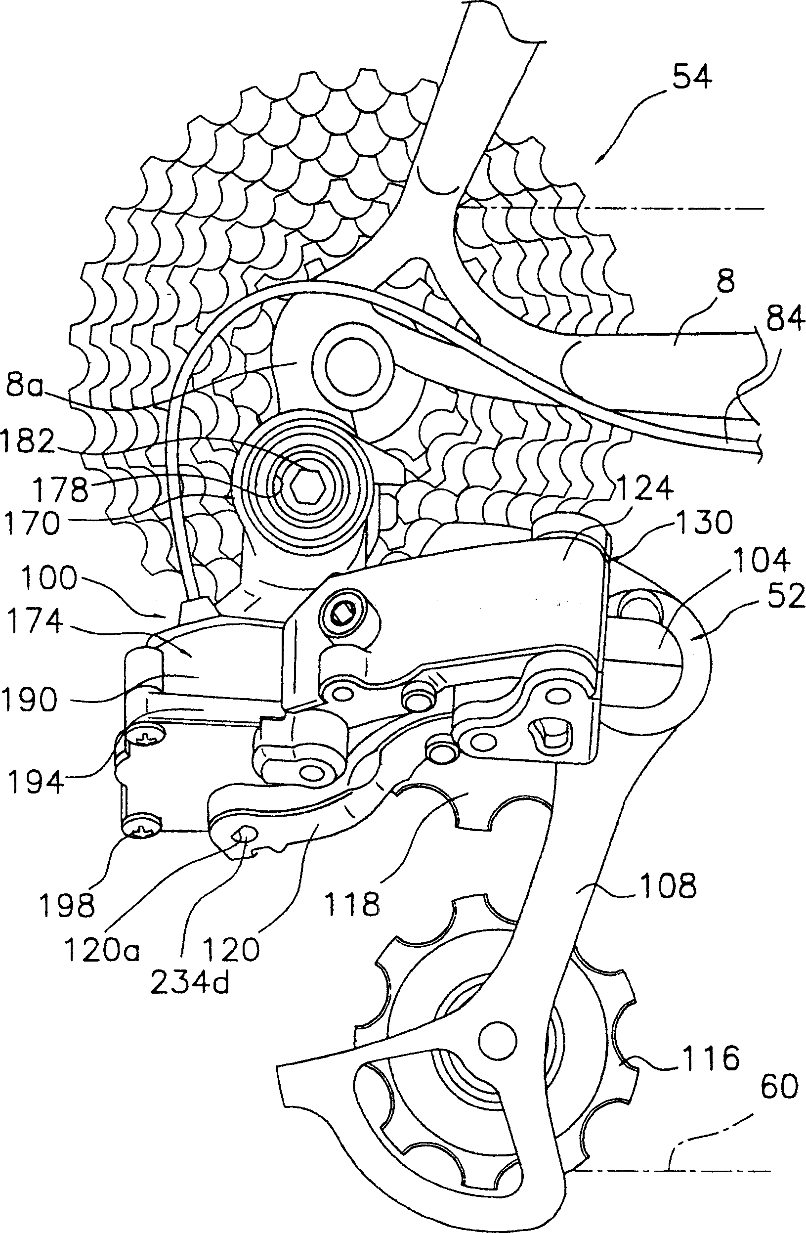
[0046] (a) In the above-mentioned embodiments, an example of the electric drive device is disclosed as the shift drive unit provided in the derailleur as the operating mechanism, but the present invention is not limited thereto, and can also be applied to And the electric drive connected to the derailleur. In addition, the operating mechanism is not limited to the rear derailleur, and the present invention can also be applied to an electric drive that electrically drives an operating mechanism such as an electric front derailleur, a suspension unit, or a traveling drive (auxiliary power unit for traveling). device.

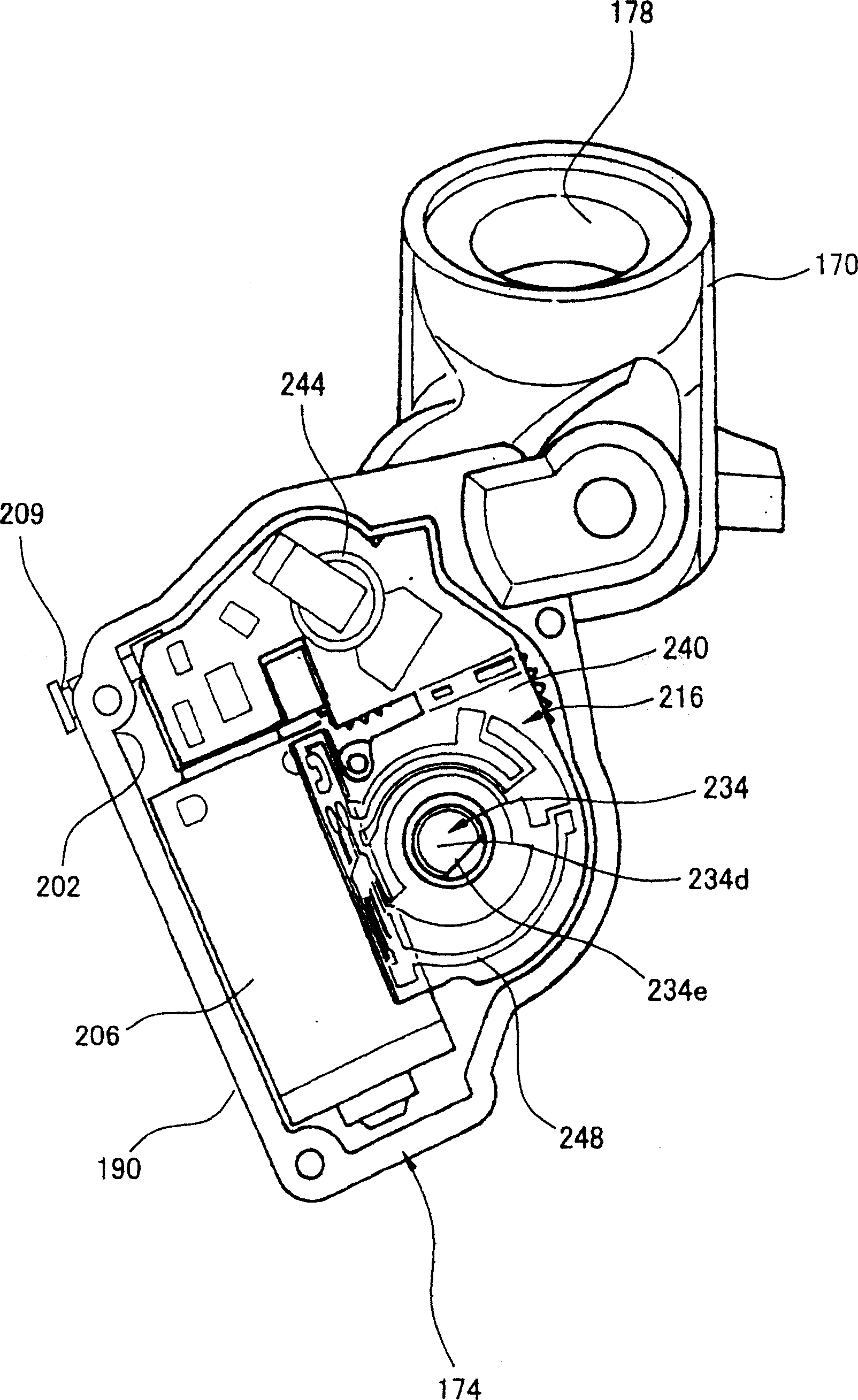
[0047] (b) In the foregoing embodiments, the contact portion 224 is in direct contact with the bearing 222 mounted on the output shaft 206a, but it may also be as Figure 7 As shown, the contact portion 224 is designed to be in contact with the bearing 222 via the bearing receiving portion 232 . exist Figure 7 Among them, the cross section of the bearing accom...


PUM


Abstract

An apparatus for inhibiting undesirable movement of a bicycle electrical component comprises a motor (206) having an output shaft (206a) that rotates around a rotational axis, a driving member (207) disposed on the output shaft, and a driven mvember (208) that is driven by the driving member. A movement control unit (209) controls movement of the output shaft in a direction other than rotation around the rotational axis (R).

Description

technical field [0001] The present invention relates to a driving device, in particular to an electric driving device for a bicycle that electrically drives an operating mechanism that can be mounted on a bicycle. Background technique [0002] Recently, various electric drive devices employing electric motors are also used in the field of bicycles. For example, electric drive devices such as electric transmissions for electrically shifting bicycles and auxiliary drives for assisting driving force of bicycles are widely used (for example, refer to Patent Document 1). A conventional electric drive device is a device that drives a front derailleur (an example of an operating mechanism) of a bicycle via a shift cable, and has: a housing member that can be mounted on the bicycle; A motor positioning unit (an example of an electric drive device) for positioning a shift cable; and a shift control unit housed in the housing member side by side with the positioning unit and controll...

Claims


Application Information

Patent Timeline
Patent Type & Authority Applications(China)
IPC IPC(8): B62M25/08B62M9/12B62M9/122H02K7/10
CPCB62M25/08F16H2057/0222B62M9/12F16H1/16F16H2057/0213B62M9/122
Inventor 福田雅彥
Owner SHIMANO INC
Why Eureka
Try Eureka