Check patentability & draft patents in minutes with Patsnap Eureka AI!

Carrying device

A conveying device and conveyor technology, applied in the direction of conveyors, vibrating conveyors, conveyor objects, etc., can solve problems such as problems that cannot be completely eliminated

Inactive Publication Date: 2006-08-16
KHS GMBH
View PDF1 Cites 0 Cited by
  • Summary
  • Abstract
  • Description
  • Claims
  • Application Information

AI Technical Summary

Problems solved by technology

Problems cannot be completely ruled out when transporting in the area of ​​such a pusher or slide

Method used


Image

  • Carrying device
  • Carrying device
  • Carrying device

Examples


Embodiment Construction

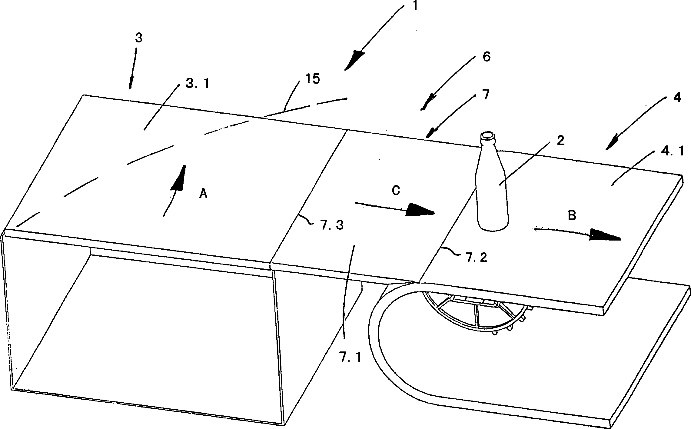
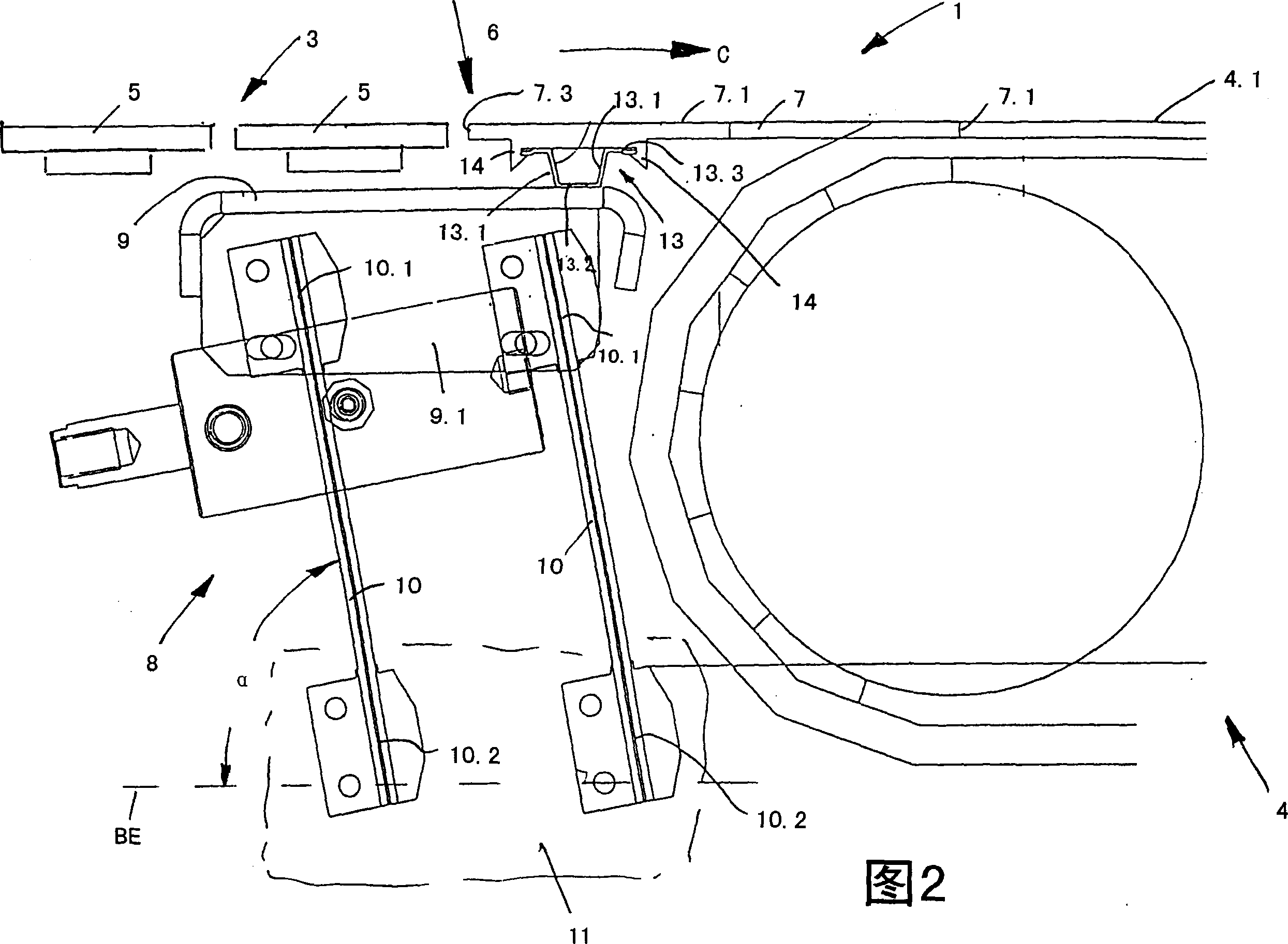
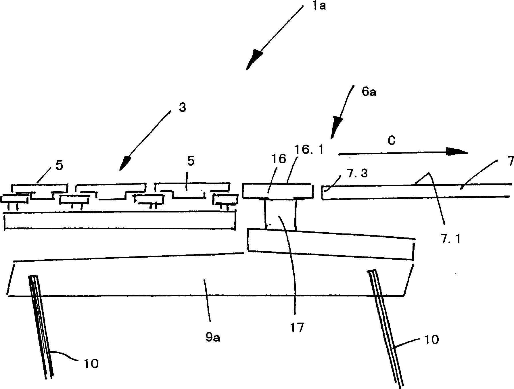
[0027] The conveying device generally indicated with 1 in the drawings for conveying bottles 2 or similar containers mainly comprises two conveyors 3 and 4, wherein the conveyor 4 is used, for example, to guide away bottles 2 from a processing machine, for example from A sterilizer (Pasteur) guides away the filled and closed bottles 2, and the conveyor 3 constitutes the transfer or conveying section of the processing machine, for example the sterilizer, on which the bottles 2 are guided to Sent through a processing machine, for example through a tunnel furnace of the sterilizer.

[0028] On the conveyors 3 and 4 or on the conveying surfaces 3.1 or 4.1 of these conveyors, the bottles 2 are respectively placed upright, that is to say with their bottle axes oriented in the vertical direction. Conveyor belts or hinged belt chains (Scharnierbandketten) connected to each other laterally (Fig. 2 and image 3 ), which are driven circumferentially by means of corresponding drives, so ...


PUM


Abstract

The invention relates to a conveyor device used for bottles or similar containers, which comprises at least two conveyors respectively used for one conveying surface of a container and following each other in a conveying section; a conveyor or an auxiliary conveyor that is used for connecting the conveying surfaces of the conveyors through a conveying surface constituted by at least one conveying component; and a vibration drive device used for making one at the least conveying component of the auxiliary conveyor oscillating movement on a horizontal axis fixed on the conveying direction of the auxiliary conveyor, wherein the vibration drive device is configured that the oscillating movement of one at the least conveying component of the auxiliary conveyor also has a vertical movement component.

Description

technical field [0001] The present invention relates to a conveying device for bottles, cans or similar containers. Background technique [0002] On conveyor sections or conveyors for bottles or similar containers it is often the case that two conveyors in the extension of the conveyor section are connected to each other and the containers are conveyed from one to the other, for example via push plates or slides. The conveyor is forwarded to the next conveyor in the conveyor segment via a push (berschieben). In the region of such push plates or slides, problems cannot be completely ruled out during transport. [0003] In order to eliminate this disadvantage, it has been disclosed (by DE 93 00 609 U1) that in the connection or transition area between the two conveyors, a transfer plate as a transfer or auxiliary conveyor is arranged, which is oscillated by a vibration drive Movement on a horizontal or nearly horizontal axis oriented in the conveying direction. But in this...

Claims


Application Information

Patent Timeline
Patent Type & Authority Applications(China)
IPC IPC(8): B65G47/66
CPCB65G47/66B65G27/10B65G2201/0244
Inventor 托尔斯滕·斯洛瓦克
Owner KHS GMBH
Features
  • R&D
  • Intellectual Property
  • Life Sciences
  • Materials
  • Tech Scout
  • Unparalleled Data Quality
  • Higher Quality Content
  • 60% Fewer Hallucinations
Learn More