Communications network

a communication network and network technology, applied in the field of communication networks, can solve the problems of significant operational task, low support of layer 3 routed applications, and inability to meet the needs of real-time management of the virtual publi

Inactive Publication Date: 2005-04-26
GENBAND US LLC
View PDF4 Cites 104 Cited by
  • Summary
  • Abstract
  • Description
  • Claims
  • Application Information

AI Technical Summary

Benefits of technology

[0005]An object of the invention is to minimise or to overcome the above disadvantages.
[0015]In a preferred embodiment of the invention, we employ a three-layer label stack at the edge of the network in order to achieve end-to-end connection oriented behaviour with guaranteed quality of service. We have found that the use of the three-layer label stack is sufficient to minimise the control of the network to the two edges of the network and a single central switching stage of the network. In this manner the real-time control constraints placed on the second and fourth stages of the network are removed thus enabling these stages to scale to extremely large capacity.
[0019]In our arrangement and method, a third level of label is employed in conjunction with a dynamic multiplex constraint-based routed label switched path (CR-LSP) in order to achieve implicit switching at certain nodes within a network. Implicit switching occurs when a switching function takes place at a node without the need for any control function being required at that node. Such an implicit switching function provides the advantages of simplifying the overall control architecture of the network and minimising the real-time processing requirements on those nodes that perform the implicit switching function. This enables very large scale nodes to be implemented while maintaining the flexibility of having switching points at those nodes.

Problems solved by technology

This of course introduces the problem of supporting different protocols over a common network.
For Internet protocol traffic however, ATM has proven to be less than fully effective at supporting Layer 3 routed applications, such as routed virtual private networks.
A particular problem with the introduction of a multi-service network is that of accommodating the various transport protocols and, in particular, that of providing end to end quality of service guarantees for high priority traffic such as voice.
A further problem with such a network is that of real time management of the virtual public / private networks that are established within the network.
In a large network this is a very significant operational task.

Method used


Image

  • Communications network
  • Communications network
  • Communications network

Examples


Embodiment Construction

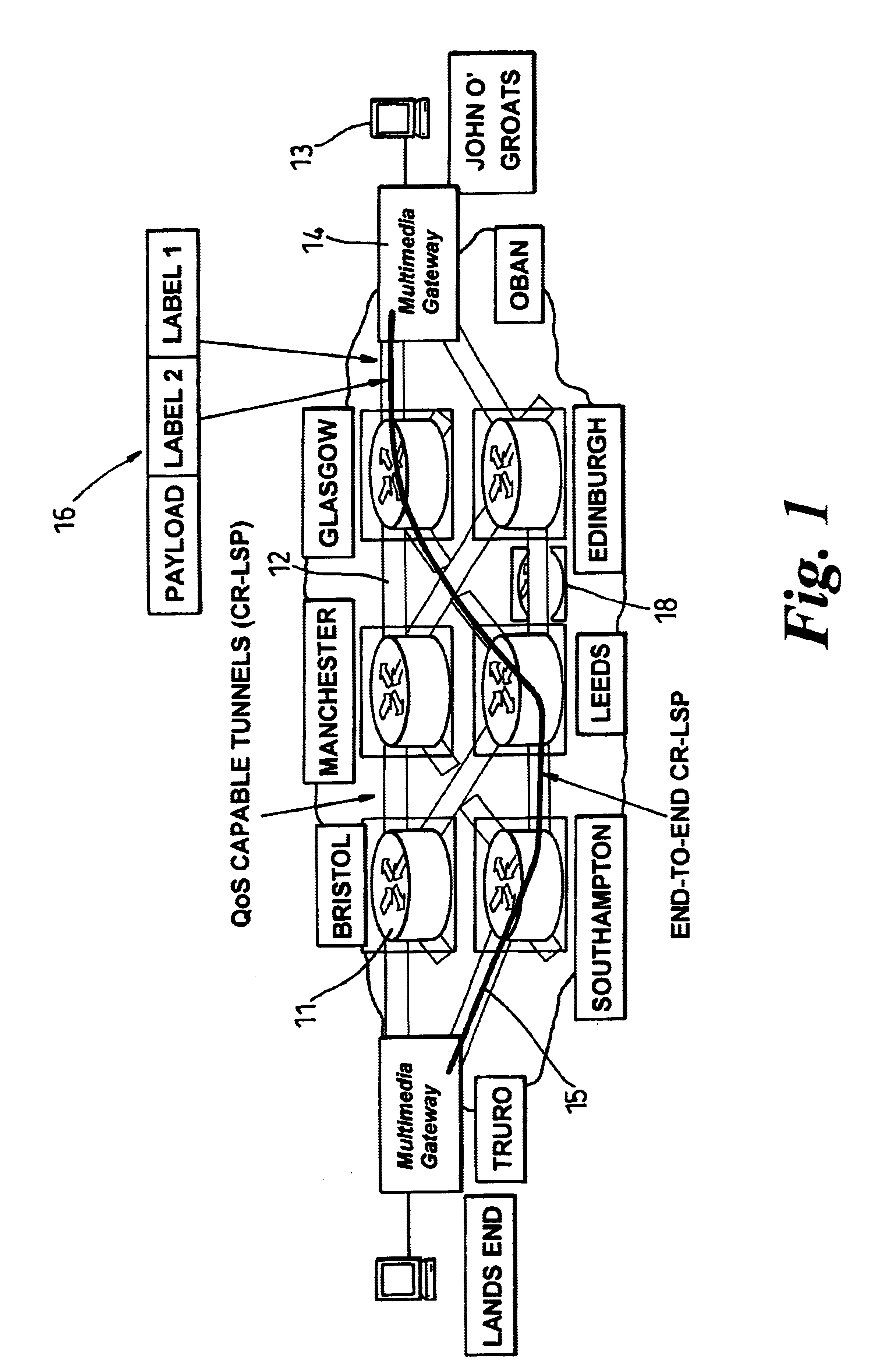
[0033]Referring first to FIG. 1, which is introduced for explanatory and comparative purposes, this figure illustrates in highly schematic form an exemplary virtual public / private network (VPN) deployed nationally or regionally in order to provide session switched multimedia services on a territorial basis. The network comprises a number of service nodes 11, located at the main centres of population, inter-linked via a network of core nodes by quality-of-service (QoS) capable tunnels 12. The construction of the core network will be described below. In FIG. 1, only one core node 18 is shown in the interests of clarity, but it will of course be appreciated that the network will incorporate a plurality of core nodes. Access to the network from user terminals 13 is provided via media gateways 14 each serving to one or more service nodes 11. Traffic is transported on constraint-based routed label switched paths (CR-LSP) 15 established between respective gateways. The network carries pack...


PUM


Abstract

In a label switch communications network, a third level of label is employed in conjunction with a dynamic multiplex constraint-based routed label switched path (CR-LSP) in order to achieve implicit switching at nodes within the network. Implicit switching occurs when a switching function takes place at a node without the need for any control function being required at that node. A three-layer label stack provided at the edge of the network achieves end-to-end connection oriented behaviour with guaranteed Quality of Service. The use of the three-layer label stack concentrates the control of the network to the two edges of the network and a single central switching stage of the network.

Description

FIELD OF THE INVENTION[0001]This invention relates to arrangements and methods for the switching or routing of traffic in a communication network.BACKGROUND OF THE INVENTION[0002]Traditionally, two types of legacy telecommunication networks have been developed. The first type of legacy network is connection oriented and is used for the transport of narrow band voice traffic, typically carried in TDM frames. Such networks comprise for example synchronous or plesiochronous networks. The second type of legacy network is connectionless in nature and is used for the transport of broad band packet or cell-based data traffic. Such packet traffic includes for example Internet protocol (IP) traffic. There is currently a drive towards unified networks which provide end to end transport for both voice and data services, and to this end the use of asynchronous transport has been introduced. This of course introduces the problem of supporting different protocols over a common network.[0003]Async...

Claims


Application Information

Patent Timeline
Patent Type & Authority Patents(United States)
IPC IPC(8): H04L12/46H04L12/56
CPCH04L45/50H04L12/4633
Inventor MAUGER, ROYSTACEY, DAVIDGIBSON, MARK
Owner GENBAND US LLC
Why Eureka
Try Eureka