Cardiac vein lead with flexible anode and method for forming same

Active Publication Date: 2006-04-18
MEDTRONIC INC
View PDF19 Cites 93 Cited by
  • Summary
  • Abstract
  • Description
  • Claims
  • Application Information

AI Technical Summary

Benefits of technology

[0009]The distal end of the coil electrode may be finished by sculpt welding the filar ends to an adjacent filar. The distal end of the coil electrode may alternatively be finished by compressing the filars and joining them to each other in a continuous radial weld. A molybdenum mandrel is preferably used during this welding process to prevent contamination of the weld pool.
[0010]The flexible coil electrod

Problems solved by technology

Cardiac vein leads are particularly difficult to implant due to the tortuous pathway encountered as the lead is advanced through the cardiac veins.
Some cardiac vein locations may therefore be inaccessible due to limitations and difficulties associated with maneuvering currently available lead systems into a narrow venous branch at an obli

Method used


Image

  • Cardiac vein lead with flexible anode and method for forming same
  • Cardiac vein lead with flexible anode and method for forming same
  • Cardiac vein lead with flexible anode and method for forming same

Examples


Embodiment Construction

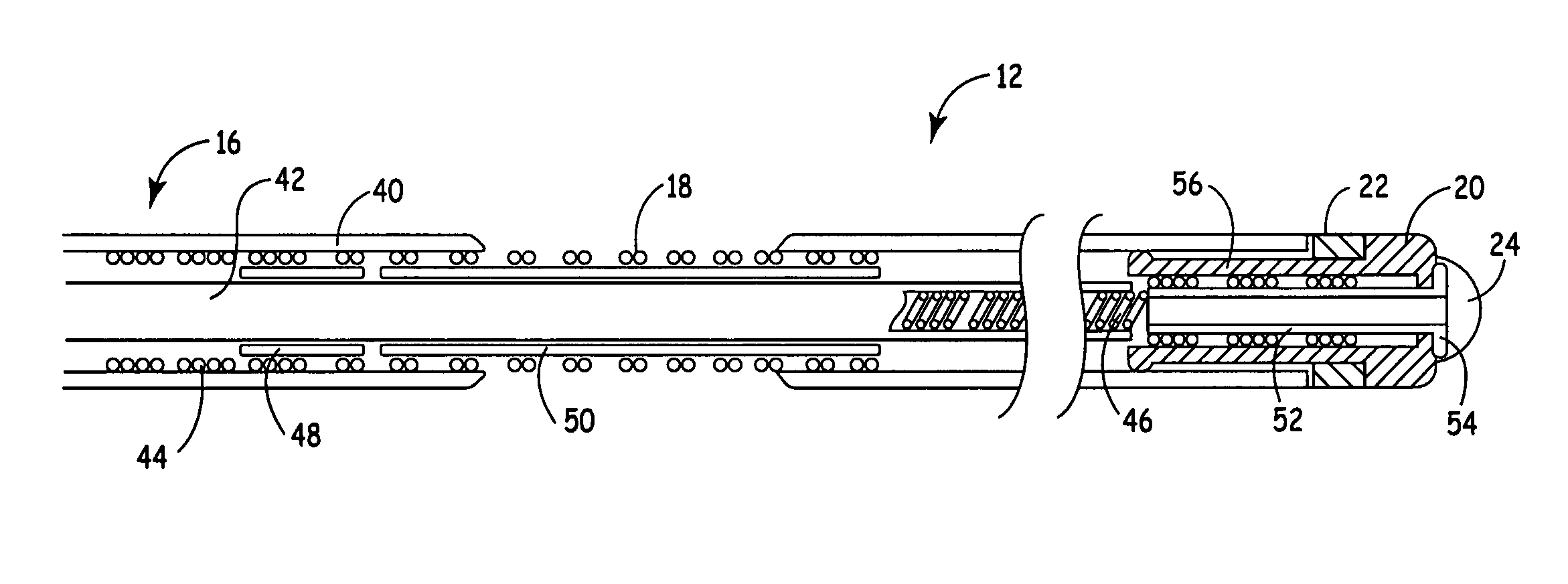
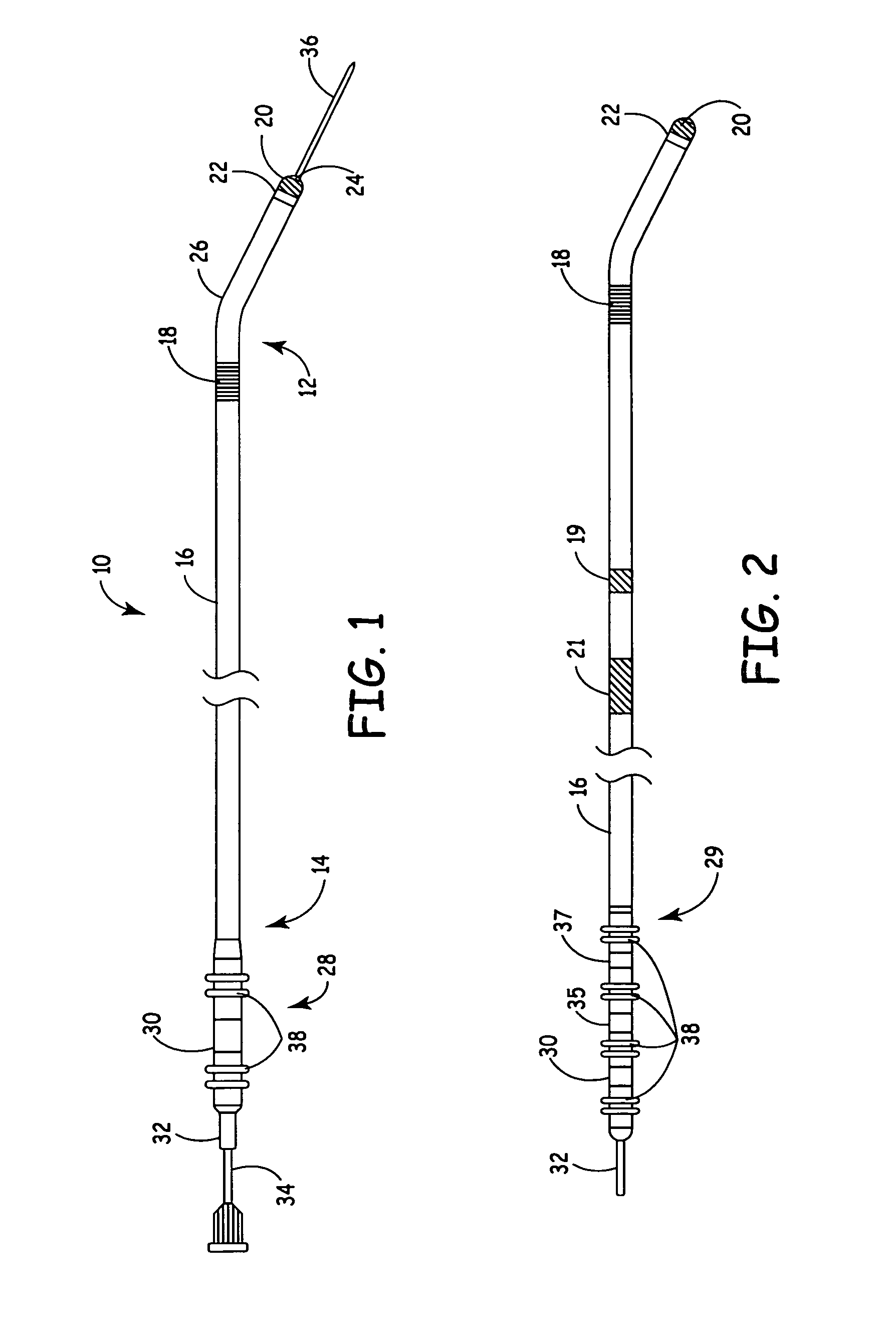
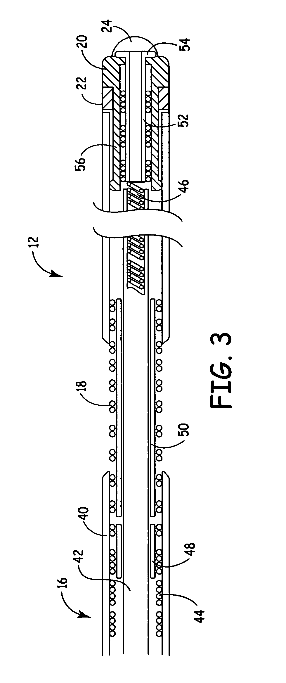
[0021]FIG. 1 is a plan view of a bipolar cardiac vein lead having a flexible coil anode electrode in accordance with the present invention. As illustrated in FIG. 1, according to the present invention, a lead 10 includes a flexible, elongated lead body 16 extending between a proximal end 14 and a distal end 12, and a tip electrode 20 positioned at distal lead end 12. Tip electrode 20 is shown in FIG. 1 as being a ring tip electrode and may resemble the ring tip electrode disclosed in U.S. Pat. No. 5,342,414 issued to Mehra, incorporated herein by reference in its entirety. However, tip electrode 20 may alternatively be provided as a generally hemispherical electrode, a helical electrode, a barb or any other tip electrode known for use in cardiac leads. A monolithic controlled release device (MCRD) 22 may optionally be provided proximal to tip electrode 20 to elute an anti-inflammatory steroid to prevent degradation of the electrical properties at the electrode-tissue interface due t...


PUM


Abstract

A bipolar cardiac vein lead and method of assembly is provided wherein the lead includes a flexible coil anode electrode such that the lead may be advanced through a tortuous pathway. The coil electrode is coupled to a conductor using a method of assembly that minimizes or eliminates rigid components, maintaining flexibility of the distal lead end. Multi-polar cardiac vein leads may include multiple flexible coil electrodes to achieve pacing and/or sensing in the left atrium and the left ventricle or at multiple left heart sites.

Description

FIELD OF THE INVENTION[0001]The present invention generally relates to medical electrical leads, and more particularly, the present invention relates to a cardiac vein lead having a flexible electrode design to allow advancement of the lead through a tortuous pathway to a desired implant site.BACKGROUND OF THE INVENTION[0002]Coronary sinus leads have been developed to achieve cardiac sensing, pacing and defibrillation in the left heart chambers. Examples of coronary sinus leads are disclosed in U.S. Pat. No. 6,321,123 B1 issued to Morris et al., and U.S. Pat. No. 5,466,254 issued to Helland. Small diameter leads that may be advanced further into the cardiac veins have been developed in order to more specifically target the left ventricle for pacing and / or sensing.[0003]Coronary sinus and cardiac vein leads are generally implanted with the use of a guide catheter and / or a guidewire or stylet to achieve proper placement of the lead. A cardiac vein lead may be placed using a multi-step...

Claims


Application Information

Patent Timeline
IPC IPC(8): A61N1/05
CPCA61N1/056A61N2001/0585
Inventor HINE, DOUGLAS S.SOMMER, JOHN L.BASS, WAYNE R.MORRIS, MARY M.MCINTYRE, PETER B.PFEIFFER, CARLA C.LAFOND, ROGERPETERSON, PATRICIA K.
Owner MEDTRONIC INC
Why Eureka
Try Eureka