Plate type wedge lateral rolling forming method for eccentric step shalf

A technology of stepped shaft and cross wedge rolling, applied in the direction of roll, metal rolling, metal rolling, etc., can solve the problem of inability to form eccentric shaft parts, etc., to improve material utilization, good quality of parts, and reduce machining costs Effect

Inactive Publication Date: 2006-08-23
UNIV OF SCI & TECH BEIJING
View PDF0 Cites 9 Cited by
  • Summary
  • Abstract
  • Description
  • Claims
  • Application Information

AI Technical Summary

Problems solved by technology

However, the traditional cross wedge rolling process can only produce various concentric rotary shaft parts, and cannot form eccentric shaft parts.

Method used


Image

  • Plate type wedge lateral rolling forming method for eccentric step shalf
  • Plate type wedge lateral rolling forming method for eccentric step shalf
  • Plate type wedge lateral rolling forming method for eccentric step shalf

Examples


Embodiment Construction

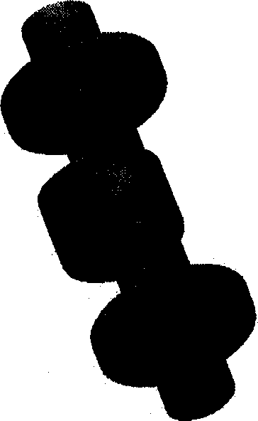
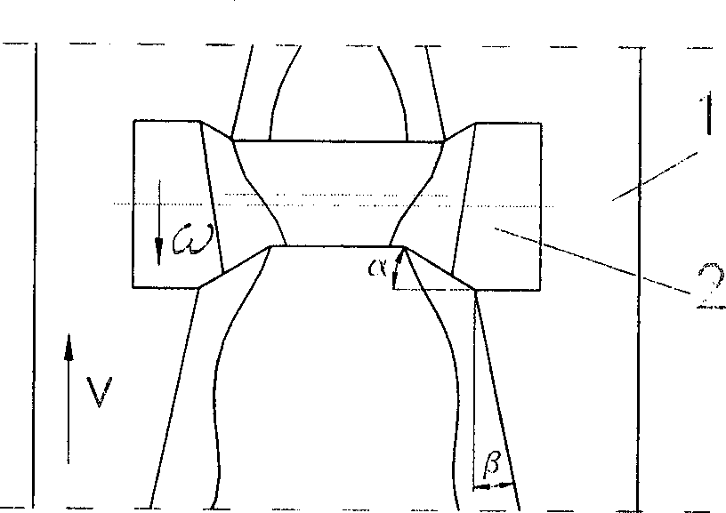
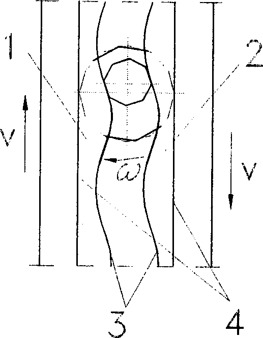
[0040] Figure 10 Shown is an example of plate cross wedge rolling forming with an eccentric shaft ( Figure 9 ) and the schematic diagram of the rolling forming process of the eccentric shaft. The blank is placed between the two moulds, and the movement of the mold drives the blank to rotate. Under the action of the mold, the blank is radially compressed and axially extended, and the blank is gradually formed into a stepped shaft. The middle diameter of the forming eccentric shaft of the I stage die is Φ30mm; the diameter of the eccentric shaft of the forming eccentric shaft of the II stage die is Φ33mm; forming at this stage is different from the traditional cross wedge rolling process, and is the key point of the present invention. In the stage of forming the eccentric shaft, the longitudinal section of the soil is as follows Figure 10 As shown in (V-V), the wedge shape of the mold corresponding to the eccentric shaft of this section is as follows Figure 4 shown. The ...


PUM


Abstract

The present invention provides a kind of plate type wedge rolling forming method for eccentric stepped shaft, and belongs to the field of plastic metal forming technology. The forming method includes moving two plate type molds with wedge mold face to face, and extruding heated circular rod in the molds for continuous radial compression and axial extending deformation to become eccentric stepped shaft gradually. The mold for forming eccentric circular shaft section has wedge work surface comprising inclined wedge surface and mold top surface, and curved top surface, with the curved surface being one corrugate envelope surface formed by the corrugate motion of the eccentric rolled workpiece circle and the mold top surface during the rolling process. The present invention has the advantages of high production efficiency, high material utilizing rate, low production cost, high size precision and high product quality, and realizes the precise formation of eccentric stepped shaft.

Description

Technical field: [0001] The invention belongs to the technical field of metal plastic forming, and in particular provides a plate type cross wedge rolling forming method of an eccentric stepped shaft. technical background: [0002] Cross-wedge rolling is a new forming process for shaft parts. Its working principle is: two plate dies with wedge-shaped dies move in opposite directions to drive the circular rolled piece to rotate in the opposite direction. Next, roll forming various stepped shafts. Its main deformation is radial compression and axial extension. This technology is mainly used for the production of large-volume shaft parts, including: shaft parts on automobiles, tractors, motorcycles, internal combustion engines, hardware tools, construction machinery, power fittings, etc. This technology has the characteristics of high efficiency, material saving and low consumption, and is an advanced production technology for saving materials and energy. However, the tradit...

Claims


Application Information

Patent Timeline
Patent Type & Authority Applications(China)
IPC IPC(8): B21H1/22B21B1/08B21B27/02
Inventor 王宝雨胡正寰刘晋平杨翠苹
Owner UNIV OF SCI & TECH BEIJING
Why Eureka
Try Eureka