
Magnetic position detecting apparatus

A detection device and relative configuration technology, applied in the direction of measuring device, using electrical device, using electromagnetic/magnetic device to transmit sensing components, etc., can solve the problems of reduced output waveform resolution, low output waveform resolution, and reduced magnetic field strength. , to achieve the effect of reducing the spacing error, reducing the area, and reducing the difference between the magnetic field strengths

Active Publication Date: 2006-08-23
NEW SHICOH MOTOR CO LTD
View PDF2 Cites 6 Cited by
  • Summary
  • Abstract
  • Description
  • Claims
  • Application Information

AI Technical Summary

Problems solved by technology

[0006] However, in the technology of Patent Document 1, since a plurality of magnetoresistive circuits of the position detection device are arranged side by side in the magnetic pole arrangement direction, when one magnetoresistive circuit has a plurality of magnetoresistive elements, or a plurality of magnetoresistive circuits are provided In the case of , there is a problem that the circuit length in the direction of the magnetic pole arrangement is long, the size of the device is large, and the resolution of the output waveform is low.
[0007] In Patent Document 2, when a plurality of magnetoresistive circuits are provided, the same problem as that of Patent Document 1 arises that the size of the position detection device increases. Image 6 As shown in (b), in the position detection device of a rotating driven body, if a longer length of the position detection device 21 in the width direction (magnetic pole arrangement direction) is adopted, the problem that occurs is that the width of the position detection device The intensity of the magnetic field received by the two ends 21a of the direction is reduced due to the position deviation, and the resolution of the output waveform is reduced

Method used


Image

  • Magnetic position detecting apparatus
  • Magnetic position detecting apparatus
  • Magnetic position detecting apparatus

Examples


Embodiment Construction

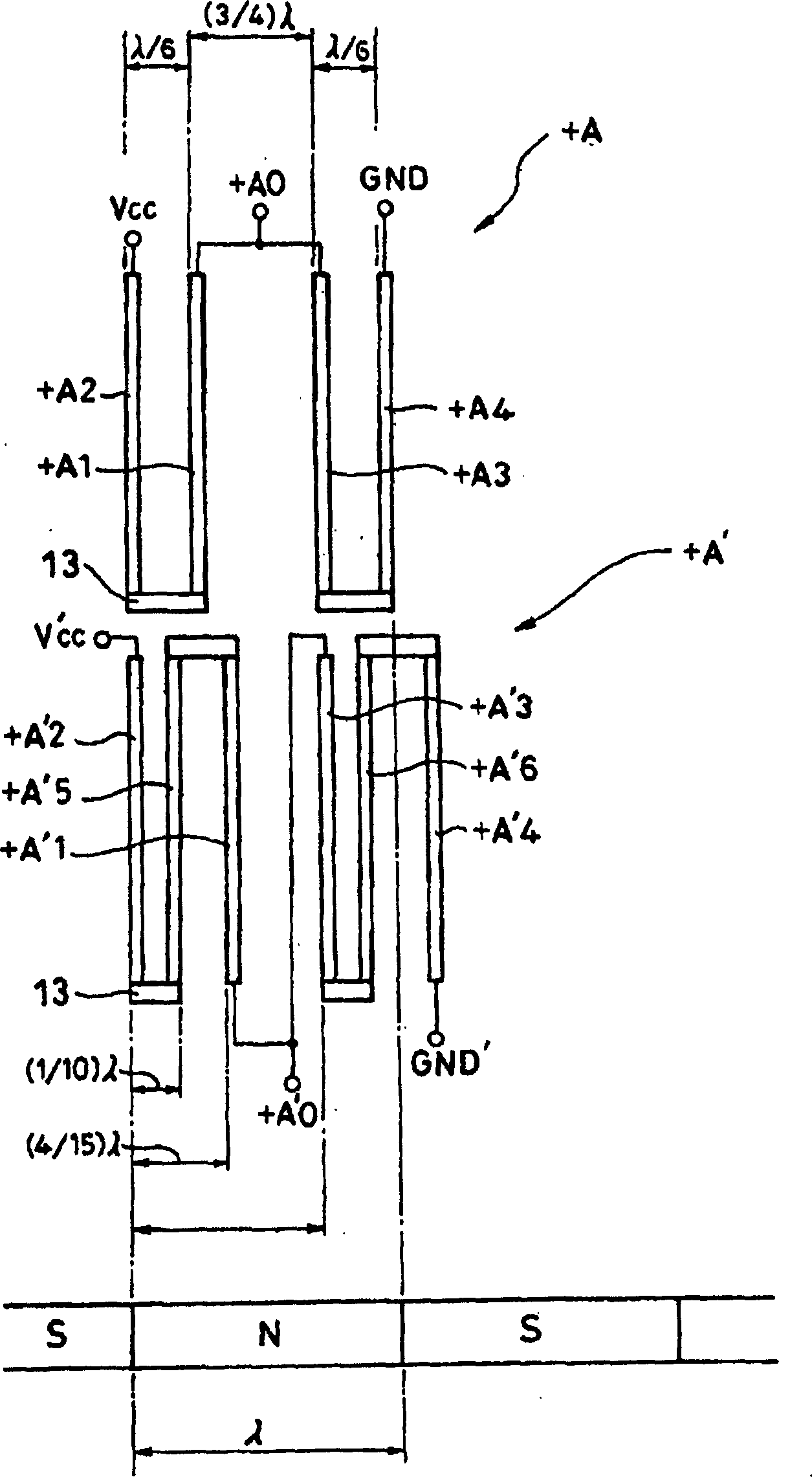
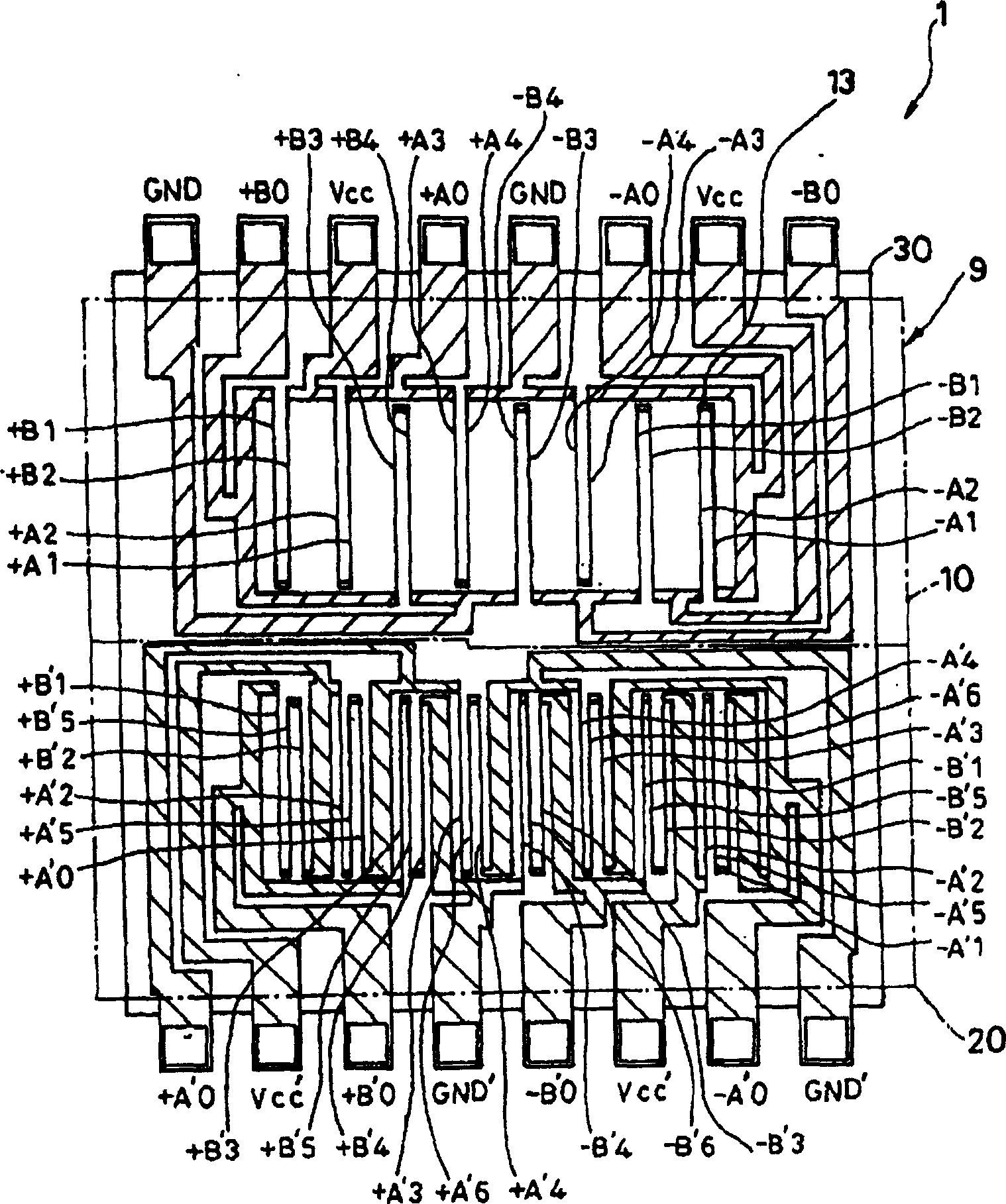
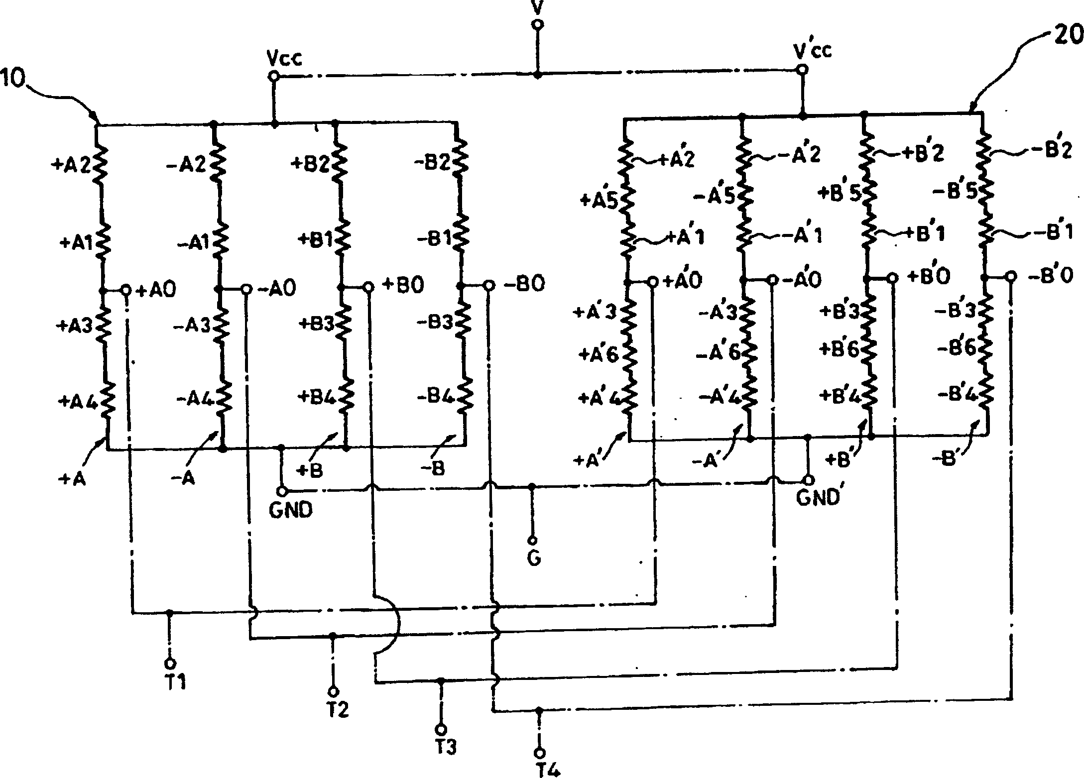
[0041] Below, refer to Figure 1 to Figure 5 Embodiments of the present invention will be described. figure 1 shown as figure 2 A plan view of the relationship of the main part of the illustrated circuit to the magnetized plane. figure 2 Shown is a plan view of a pattern circuit of the position detecting device according to the first embodiment of the present invention. image 3 for figure 2 The equivalent circuit diagram of the position detection device shown. Figure 4 for from figure 2 The output waveform diagram obtained by the position detection device is shown. Figure 5 It is a schematic perspective view showing the use state of the position detecting device according to the first embodiment.

[0042] The position detection device 1 according to this embodiment is, for example, a detection device for detecting the position of a zoom lens or a focus lens of an auto-focus camera incorporated in a mobile phone. on camera as Figure 5 As shown, a magnetized sur...


PUM


Abstract

In a position detecting apparatus 1 of the present invention, magnetic resistance circuits A and B of a first main circuit 10 include a reference magnetic resistance element +A, an even harmonic correction magnetic resistance element +A 3, being placed at a position shifted by (1 / 4)lambda or (3 / 4)lambda from the reference magnetic resistance element +A, with respect to a reference wave, and a third harmonic correction magnetic resistance element +A 2, being placed at a position shifted by (1 / 6)lambda from the reference magnetic resistance element, with respect to a reference wave, and magnetic resistance circuits A' and B' of a second main circuit 20 include the magnetic resistance circuit of the second main circuit 20 includes a reference magnetic resistance element +A' 1, a fifth harmonic correction magnetic resistance element +A' 2, being placed at a position shifted by (1 / 10)lambda from the adjacent magnetic resistance element, with respect to a reference wave and a fifth harmonic correction magnetic resistance element +A' 2, being placed at a position shifted by (4 / 15)lambda from the reference magnetic resistance element +A' 1, with respect to a third harmonic wave.

Description

technical field [0001] The present invention relates to a position detection device that detects the position of a driven body that moves linearly or rotates, and particularly relates to a position detection device that utilizes magnetism. Background technique [0002] As such a position detection device, Patent Document 1 discloses a structure in which one and the other magnetoresistive circuits formed by connecting a plurality of magnetoresistive elements in series are formed into comb teeth, and one and the other magnetoresistive circuits are formed The resistance circuits are arranged laterally side by side along the magnetic pole arrangement direction. [0003] Patent Document 2 also discloses a technique of forming a groove on the magnetized surface to adjust the output waveform of the reluctance circuit from the reference position. [0004] [Patent Document 1] Japanese Patent Publication No. 54-41335 [0005] [Patent Document 2] JP-A-7-4987 [0006] However, in the...

Claims


Application Information

Patent Timeline
Patent Type & Authority Applications(China)
IPC IPC(8): G01B7/00G01D5/12
CPCG01D5/00G01D5/24476G01D5/24485G01D5/2451G01D5/12
Inventor 白木学多田纯一
Owner NEW SHICOH MOTOR CO LTD
Learn More