
Aluminum heat exchanger

A heat exchanger, strip technology, used in heat exchange equipment, indirect heat exchangers, heat exchanger shells, etc., can solve problems such as flat tube leakage

Inactive Publication Date: 2006-08-23
T RAD CO LTD
View PDF0 Cites 3 Cited by
  • Summary
  • Abstract
  • Description
  • Claims
  • Application Information

AI Technical Summary

Problems solved by technology

That is, there may be cases where a leak occurs at the junction of the flat tubes

Method used


Image

  • Aluminum heat exchanger
  • Aluminum heat exchanger
  • Aluminum heat exchanger

Examples


Embodiment Construction

[0021] Embodiments of the present invention are described below with reference to the drawings.

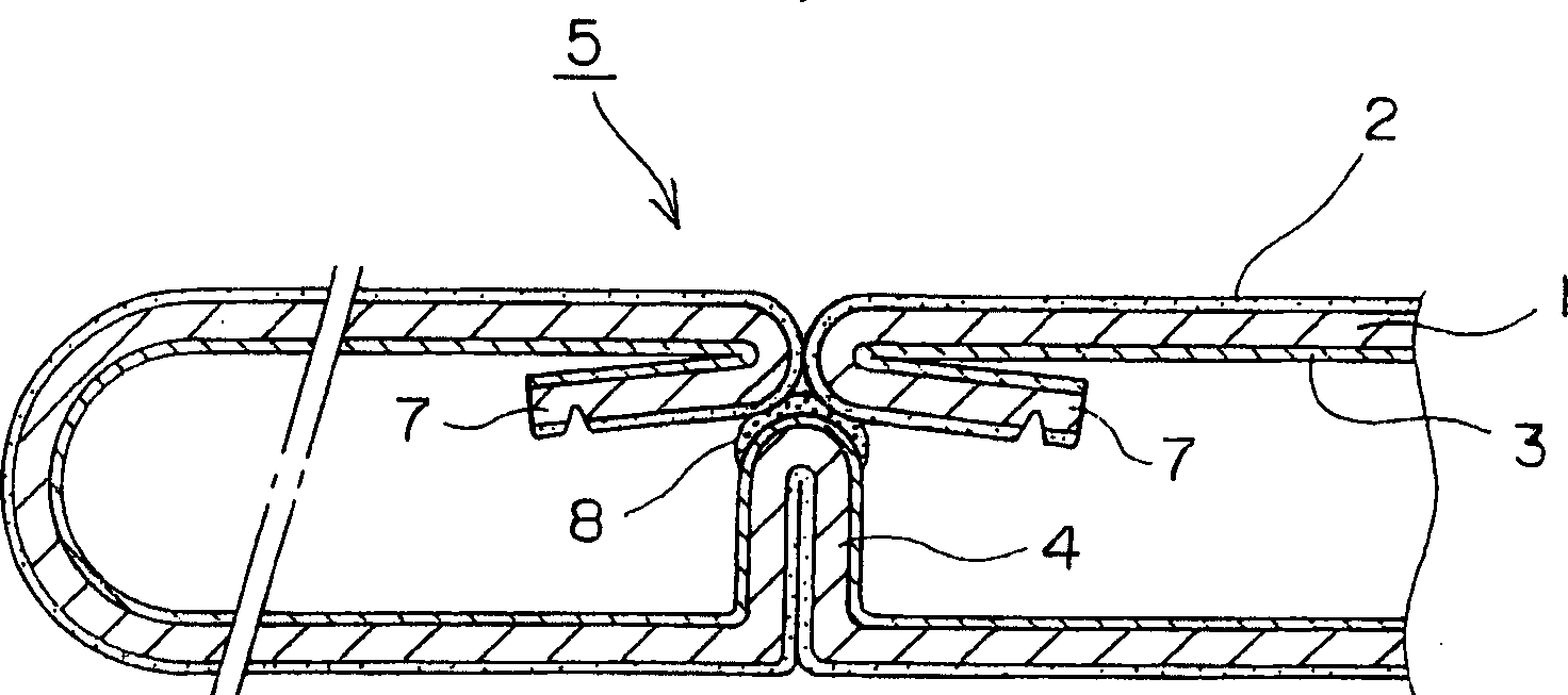
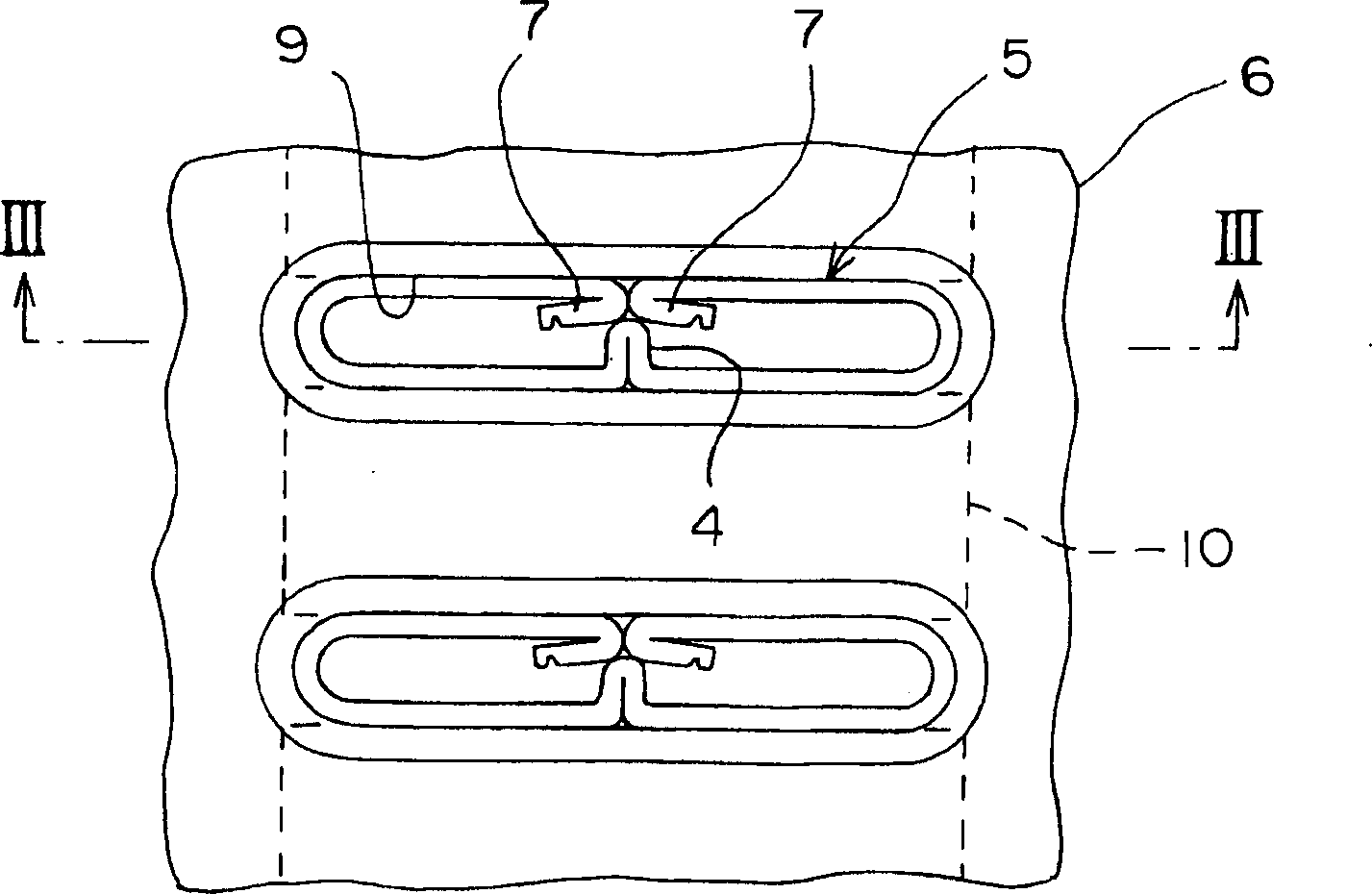
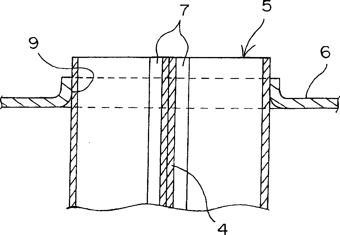
[0022] figure 1 An enlarged view showing flat tubes for an aluminum heat exchanger according to the present invention, showing relevant parts before brazing; figure 2 Represents a plan view of the heat exchanger, showing its assembled state; image 3 means along figure 2 The schematic sectional view obtained by the line III-III in ; and Figure 4 Denotes a front view showing the relevant part of the heat exchanger.

[0023] Such as Figure 4 As shown in , the heat exchanger has a plurality of flat tubes 5 arranged parallel to each other at a certain interval, and corrugated fins 10 arranged between the flat tubes 5 , and both ends of the corresponding flat tubes 5 are inserted into the tube sheet 6 The tube is inserted into the hole; the core is thus assembled.

[0024] Such as figure 1 with 2 As shown in , the flat tube 5 is formed, for example, by bending a strip mater...


PUM

PropertyMeasurementUnit
strengthaaaaaaaaaa

Abstract

An aluminum-made heat exchanger including a flat tube 5 is formed by, using an aluminum strip-shaped material coated with a brazing metal 2 on the outer surface of a core metal 1 and coated with a sacrificial anode material 3 at the inner surface side thereof, bending the strip-shaped material in the width direction thereof, wherein many flat tubes 5 are disposed parallel with each other and joined using a flux in a furnace. In order to provide the aluminum-made heat exchanger capable of being satisfactorily brazed and a high strength after brazing, the brazing metal 2 is of an Al-Si alloy, core metal 1 is an Al-Si alloy including Si of 0.4 to 1.2% by weight, and the sacrificial anode material 3 is of an Al-Mg-Zn alloy including Mg of 0.3 to 0.75% by weight.

Description

technical field [0001] The present invention relates to an aluminum heat exchanger manufactured in such a way that an aluminum strip material with metal solder and sacrificial anode material on a core metal is bent across its width to Flat tubes are formed; a plurality of flat tubes are arranged in parallel to each other to configure the core of the heat exchanger, and then undergo brazing in a furnace using a brazing flux to integrally fix the core of the heat exchanger. Background technique [0002] There is known an aluminum heat exchanger manufactured by bending a strip material coated with metal solder on the outer surface, and its seams are integrally joined with metal solder. [0003] Also, there is known a flat tube formed into a B-like shape in cross section. The flat tubes coated with metal solder on the outer surface as described above are arranged parallel to each other at the same interval; and the corrugated fins are arranged between the flat tubes; and both e...

Claims


Application Information

Patent Timeline
Patent Type & Authority Applications(China)
IPC IPC(8): F28F21/00F28F19/06C22C21/00B21C37/083B21C37/09B23K35/14B23K35/22B23K35/28C23F13/00F28D1/03F28D1/053F28F1/02F28F1/30F28F1/32F28F9/16F28F21/08
CPCB21C37/083F28F21/084B21C37/09F28D1/0391F28F21/089F28F19/06C22C21/06C22C21/00F28F1/022F28D1/0535
Inventor 伊神多加司
Owner T RAD CO LTD
Learn More