
Avascularization ring

A technology for expelling blood and ring body, applied in the field of expelling blood ring, can solve the problems of complex structure and difficult use of the tourniquet for expelling blood itself, and achieve the effects of convenient manufacture, convenient clinical operation and use, and reasonable structure.

Inactive Publication Date: 2006-08-30
张铭
View PDF1 Cites 3 Cited by
  • Summary
  • Abstract
  • Description
  • Claims
  • Application Information

AI Technical Summary

Problems solved by technology

Using this kind of blood expelling tourniquet is more convenient than the current clinically used blood expelling belt that needs to be wound, but it is still not easy to use. First, a stocking-type elastic band should be put on the limb, and then the two nylon drawstrings should be pulled evenly , it is still troublesome, and the structure of this blood-expelling tourniquet is more complicated

Method used


Image

  • Avascularization ring
  • Avascularization ring

Examples


Embodiment Construction

[0010] The present invention will be further described below in conjunction with the embodiments and with reference to the accompanying drawings.

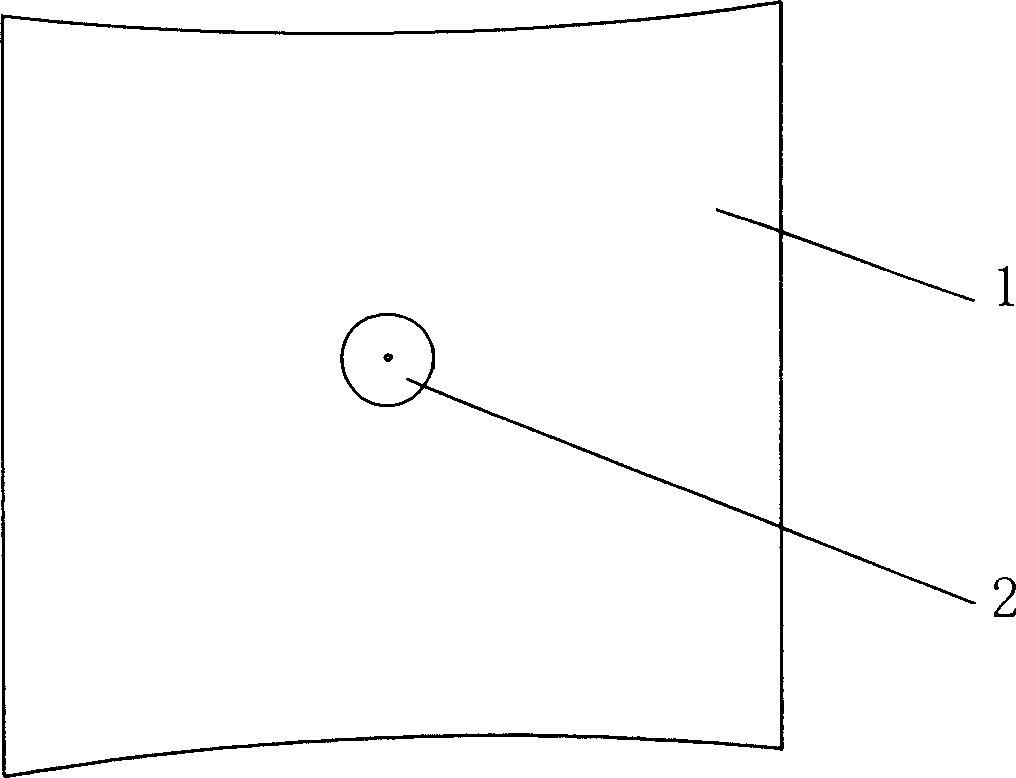
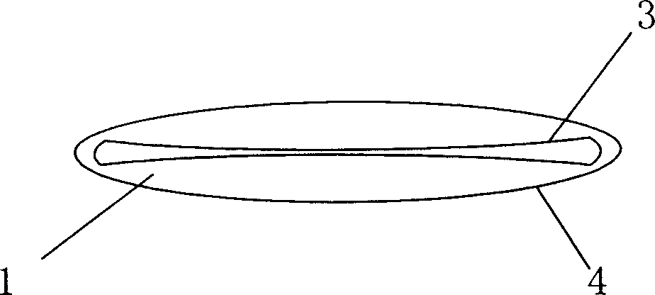
[0011] see figure 1 , The embodiment of the blood expelling ring includes a ring body 1 and a valve 2, the valve 2 is mounted on the ring body 1, and the valve 2 and the ring body 1 are airtightly connected. Embodiment ring body 1 is a sealing ring body, see figure 2 , the ring body 1 is composed of an inner ring 3 and an outer ring 4, there is a gap between the inner ring 3 and the outer ring 4, and the circumference of the inner ring 3 and the outer ring 4 are equal. Embodiment The ring body 1 is made of silicone rubber, which is convenient for high-temperature and high-pressure disinfection of the blood-draining ring, and because of the stretchability of the silicone rubber, it can achieve the same perimeter of the inner ring 3 and the outer ring 4, which is convenient for the blood-draining ring to roll during use.

[0012] ...


PUM


Abstract

A blood driving ring for clinical surgical operation is composed of a ring body which is a sealed one consisting of internal and external rings and an air valve installed on said ring body in air-tight mode.

Description

technical field [0001] The invention relates to a surgical medical instrument, in particular to a blood-expelling ring used for expelling blood from extremities during clinical surgical operations. Background technique [0002] At present, blood expelling belts are mostly used in exsanguination of extremities during surgical operations, and medical personnel clinically wrap them around the extremities that need to be expelled, which is time-consuming and laborious, and the effect of exsanguination is difficult to control. Chinese patent CN200310121103.5 "Blood-expelling tourniquet" discloses a blood-expelling tourniquet composed of a silicone rubber ring, an elastic band and a nylon drawstring. Wrapped in the elastic band, the two ends of the two nylon drawstrings are respectively fixed outside the upper end of the elastic band. When in use, the silicone rubber ring is pulled from the distal end of the limb to the proximal end of the limb by using the elastic band and the n...

Claims


Application Information

Patent Timeline
Patent Type & Authority Applications(China)
IPC IPC(8): A61B17/135
Inventor 张铭
Owner 张铭
Learn More