Pneumatic mechanical hand clamping tongs

A technology of pneumatic manipulators and clamps, applied in manipulators, chucks, manufacturing tools, etc., can solve problems such as inconvenience of manipulators, and achieve the effects of simple installation and adjustment, flexible operation, and convenient and quick loading and unloading.

Inactive Publication Date: 2006-08-30
SHANDONG UNIV OF SCI & TECH
View PDF0 Cites 54 Cited by
  • Summary
  • Abstract
  • Description
  • Claims
  • Application Information

AI Technical Summary

Problems solved by technology

[0004] At present, there is no special manipulator clamp suitable for the manipulator to grab various tools and hardware in the live maintenance

Method used


Image

  • Pneumatic mechanical hand clamping tongs
  • Pneumatic mechanical hand clamping tongs

Examples


Embodiment Construction

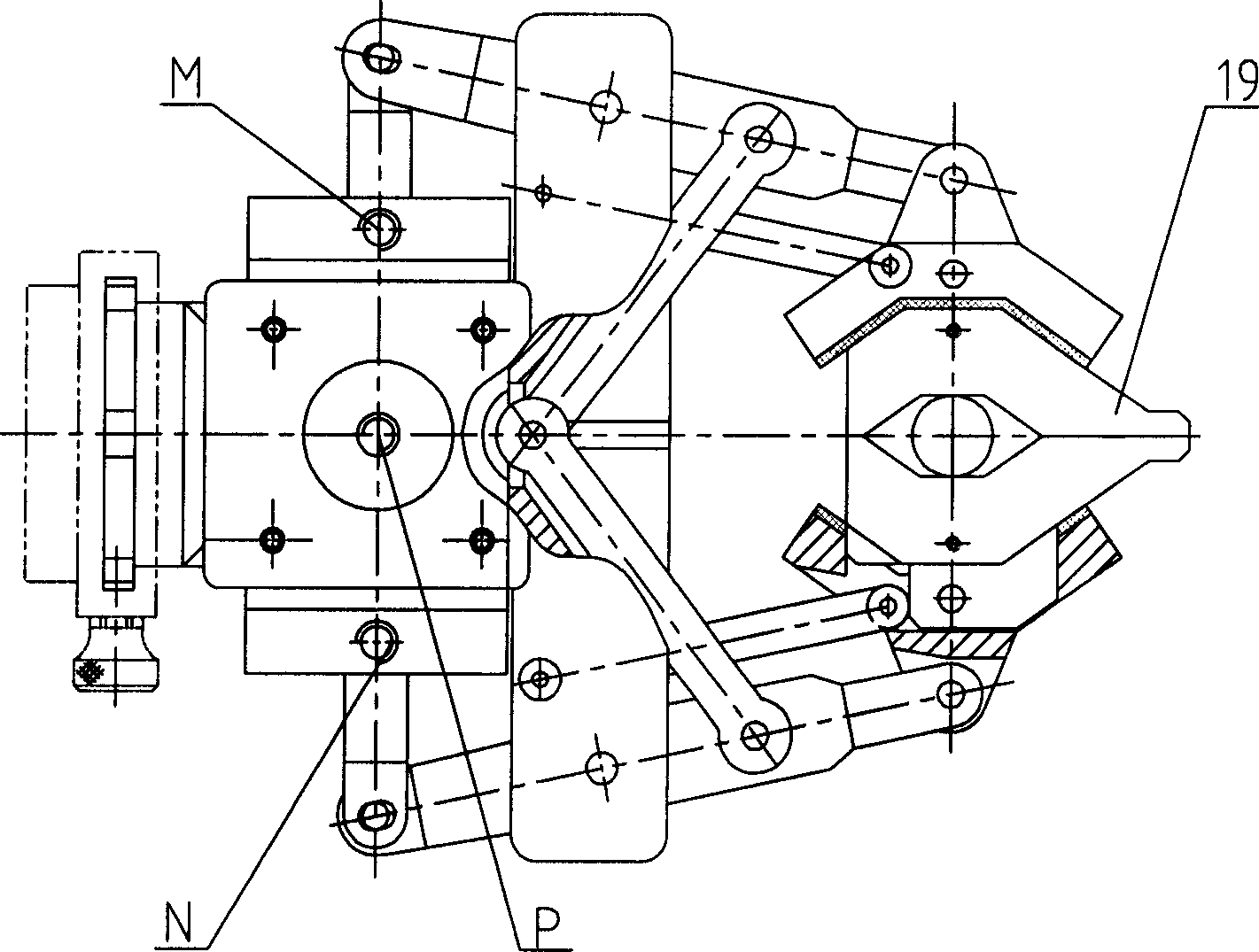
[0013] Describe the implementation process in detail in conjunction with the accompanying drawings.

[0014] Such as figure 1 , figure 2 Shown:

[0015] The rear part of the base 4 is provided with a joint 8 connected to the end interface of the manipulator, and there are 4 uniformly distributed outer convex ribs on the periphery, which are matched with the inner circular groove of the manipulator standard interface 10 and the outer ribs with 4 uniformly distributed notches, and then The whole clamp can be installed on the end of the manipulator conveniently and quickly by hand with the set screw 9; a hole for fixing the cylinder body is arranged in the middle of the block structure on the left side, which is convenient for adjusting the position of the two-way pneumatic cylinder and ensuring the symmetrical movement of the piston rod 7. The right end is provided with the pin hole of the finger support pin 13 of the finger arm 2, the pin hole connecting the pull bar 3, and ...


PUM


Abstract

The present invention belongs to the field of robot gripper, in particular, it relates to a robot pneumatic gripper. It is composed of base, two-way drive cylinder, profiling finger, finger arm, balancing drawbar and auxiliary finger. Said invention also provides their connection mode and the working principle of said pneumatic robot gripper.

Description

1. Technical field [0001] The invention relates to the field of manipulator clamps, in particular to a manipulator pneumatic clamp suitable for grasping various tools and hardware in the maintenance of urban power distribution lines. 2. Background technology [0002] Manipulator grippers have various forms such as electric, hydraulic, and pneumatic, and their structures basically use various linkage mechanisms to grasp objects of different weights, shapes, and sizes. Its application is highly targeted. [0003] Objects to be grasped during live maintenance of distribution lines include insulators, drop switches, lightning arresters, cables, various tools, rods and other accessory parts, some of which are round objects with different diameters, and some objects It is a multi-layer object with a circular groove and an annular surface, as well as some other irregular block objects. [0004] At present, there is no special manipulator clamp suitable for the manipulator to grab...

Claims


Application Information

Patent Timeline
IPC IPC(8): B25J15/08
Inventor 戴炬张志兵朱苏宁
Owner SHANDONG UNIV OF SCI & TECH
Why Eureka
Try Eureka