Weight of elevator

A technology of counterweights and elevators, applied in elevators, lifting equipment in mines, mechanical equipment, etc., can solve the problems of not easy to transport to the desired destination, and excessive weight of counterweight materials.

Inactive Publication Date: 2006-08-30
京旻重块株式会社
View PDF0 Cites 9 Cited by
  • Summary
  • Abstract
  • Description
  • Claims
  • Application Information

AI Technical Summary

Problems solved by technology

[0004] However, since the traditional weight material needs to be dried for 3-7 days before being made and used, it takes a long period of time to dry the material
Also, traditional counterweight materials are not easy to transport to the desired destination due to their heavy weight

Method used


Image

  • Weight of elevator
  • Weight of elevator
  • Weight of elevator

Examples


Embodiment Construction

[0021] specific implementation plan

[0022] Preferred embodiments of the present invention will be described below with reference to the accompanying drawings.

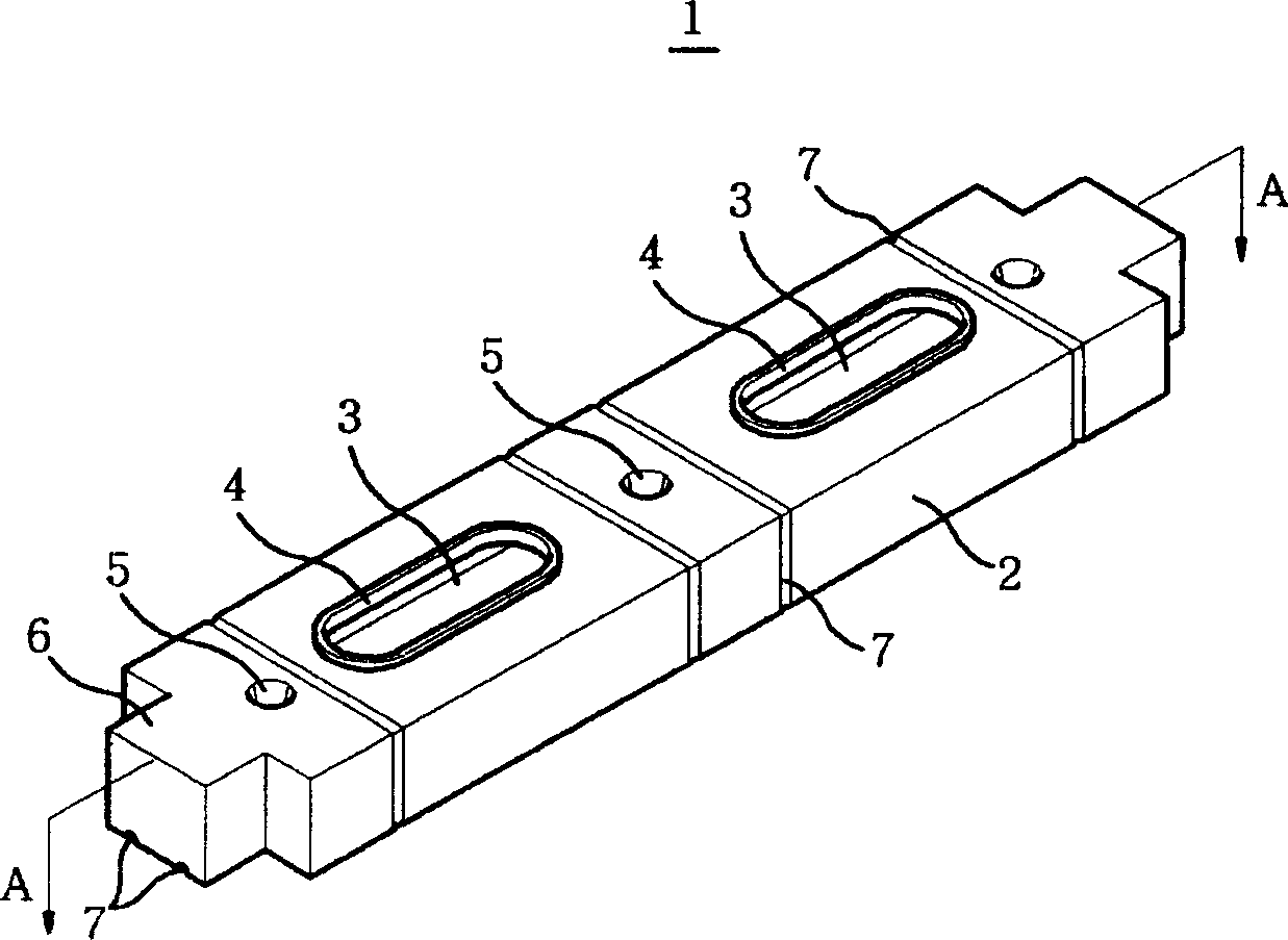
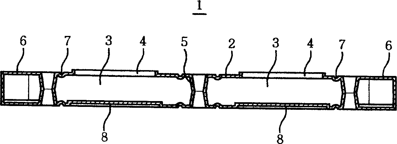
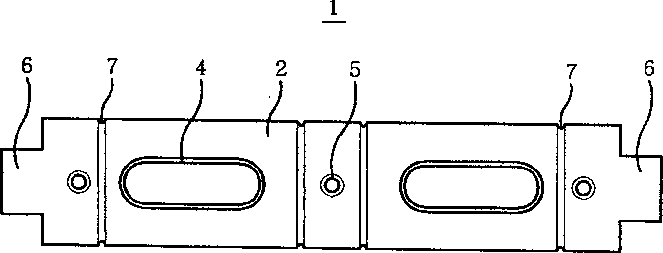
[0023] figure 1 is a perspective view showing an elevator counterweight according to the present invention, figure 2 It is shown along the elevator counterweight of the present invention figure 1 A cross-sectional view taken at line A-A in, image 3 is a plan view showing an elevator counterweight according to the present invention, Figure 4 is a bottom view showing an elevator counterweight according to the present invention, Figure 5 The view of shows the installation state of the elevator counterweight according to the present invention, Figure 6 The view of shows an elevator counterweight according to another embodiment of the present invention, Figure 7 The view of shows the handle formed on the protrusion of the weight according to the invention, and Figure 8 The view of shows another embodiment of...


PUM


Abstract

The invention relates to a lifter weighting block, especially used in the lifter with up and down operations, wherein said weighting block comprises: a frame filled with cement mixture and in long shape; a inlet on the upper side surface of frame to fill the cement mixture; a support inside the frame to hold the chamber that filled with cement mixture; and the protrusions from on two ends of frame inserted into the guide device of lifter; when several frames are carried to the lifter on-site to be layered, and filled with cement mixture. The invention can avoid directly move weight block.

Description

field of invention [0001] The present invention relates to an elevator counterweight, and more particularly to an elevator counterweight suitable for achieving the desired balance of an elevator typically designed to move up and down. Background technique [0002] Counterweights suitable for achieving specific balance in conventional elevators, press machines, flywheels of prime movers, various machines and equipment are made of cast steel or have a viscosity of 7.6 to 7.8 made of cast iron. When melting and casting the weights, the loss of steel may increase due to contamination or technical problems of engineers, thus complicating the production line. The corresponding equipment and the total cost required for the equipment increase accordingly. As a result, the price of the counterweight product increases, leading to an increase in the cost of the system. [0003] Korean Patent Laid-Open No. 1981-0002076 (publication date: December 27, 1981) entitled "Counterweight Mat...

Claims


Application Information

Patent Timeline
Patent Type & Authority Applications(China)
IPC IPC(8): B66B17/12B66B7/00B66B11/00
CPCB60R16/0215F16B2/20F16B5/0008
Inventor 张泽龙
Owner 京旻重块株式会社
Why Eureka
Try Eureka