
Non-reversible circuit component and sending/receiving module using the same

A technology of circuit components and electrode bodies, which is applied in the direction of electrical components, circuits, waveguide devices, etc., can solve the problems of large cost, complicated wiring pattern 57 winding, and insufficient freedom of wiring patterns, etc., and achieves easy installation operations Effect

Inactive Publication Date: 2006-08-30
ALPS ALPINE CO LTD
View PDF0 Cites 7 Cited by
  • Summary
  • Abstract
  • Description
  • Claims
  • Application Information

AI Technical Summary

Problems solved by technology

[0008] However, in the conventional transceiver module, since the through-hole 56a is provided in the circuit board 56, the wiring pattern 57 cannot be provided in the through-hole 56a, and not only the wiring of the wiring pattern 57 is complicated, but also the circuit board 56 having a relatively wide width is required. , and become large and costly. In addition, the wiring of the non-reciprocal circuit element is unified, and the wiring pattern of the circuit board cannot obtain a sufficient degree of freedom.
[0009] In the conventional non-reciprocal circuit element, since the input and output ends 53a of the center conductor 53 made of thin metal plates protrude outward from the first and second yokes 51 and 52, large damage to the input and output ends 53a is likely to occur during transportation and the like. The bending or deformation of the transmitter and receiver module needs to be corrected when mounting the conventional circuit board of the transceiver module. At the same time, since the input and output terminals 53a are arranged at intervals of 120 degrees, there is a unified wiring to the circuit board and the circuit board The problem that the wiring pattern cannot get enough degrees of freedom
[0010] In the conventional transmitting and receiving module, since the through-hole 56a is provided in the circuit board 56, the wiring pattern 57 cannot be provided in the through-hole 56a. Not only the wiring of the wiring pattern 57 is complicated, but also the circuit board 56 with a relatively wide width is required. In addition, the wiring of the non-reciprocal circuit element is unified and the wiring pattern of the circuit board cannot obtain a sufficient degree of freedom.

Method used


Image

  • Non-reversible circuit component and sending/receiving module using the same
  • Non-reversible circuit component and sending/receiving module using the same
  • Non-reversible circuit component and sending/receiving module using the same

Examples


Embodiment Construction

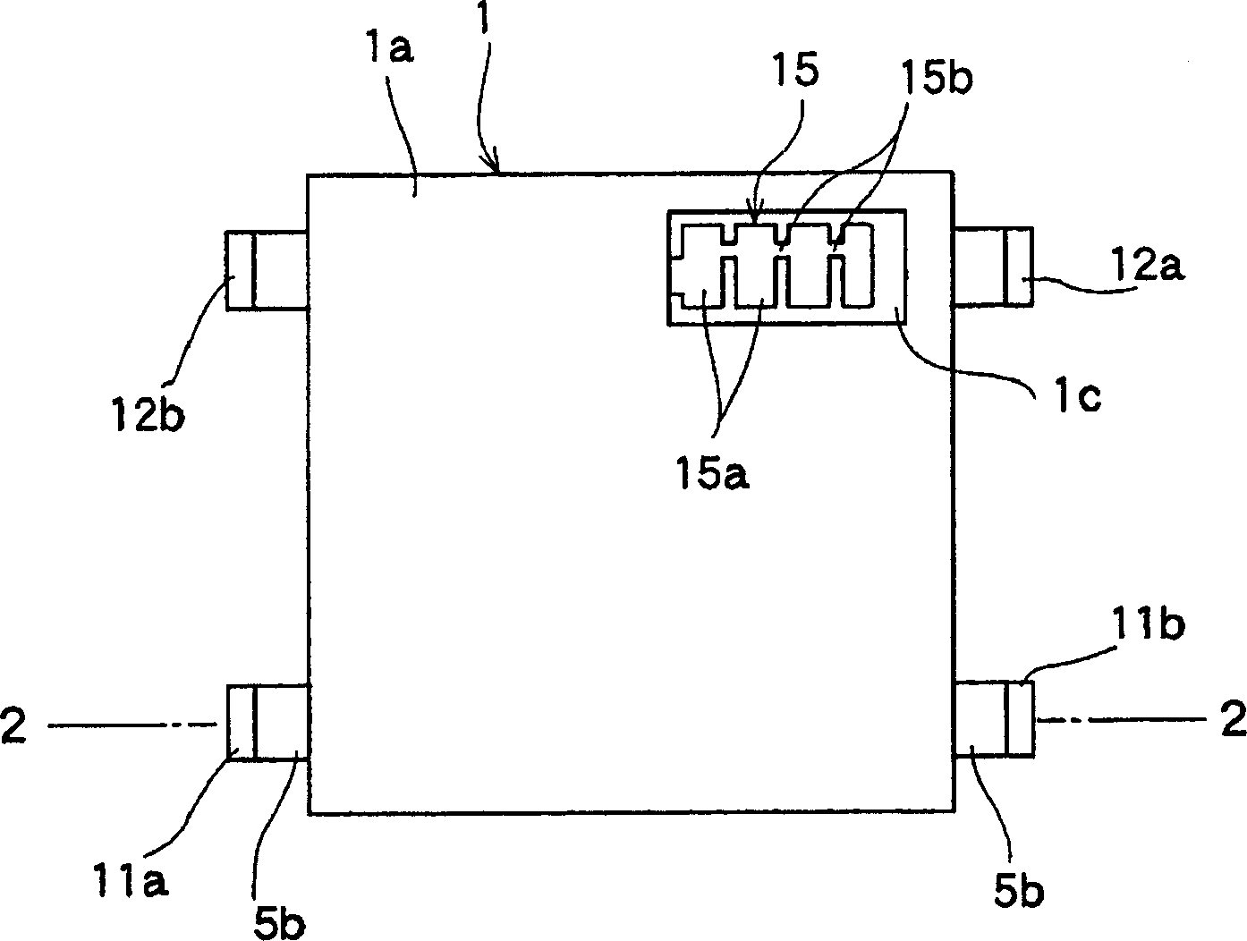
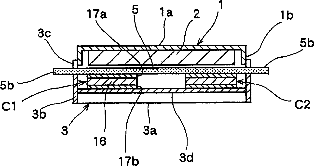
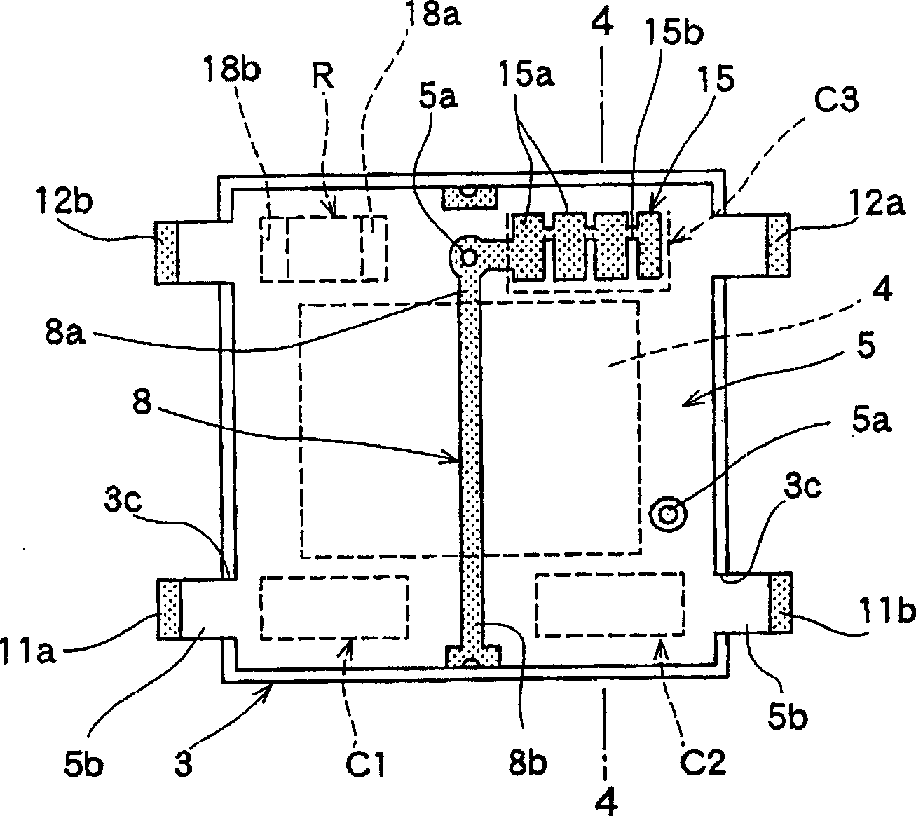
[0048] Describe the drawings of the non-reciprocal circuit element of the present invention and the transceiver module using the non-reciprocal circuit element, then figure 1 Is a plan view showing the first embodiment of the non-reciprocal circuit element of the present invention, figure 2 Yes means figure 1 The cross-sectional view in line 2-2, image 3 It is a plan view showing the state of the first embodiment of the non-reciprocal circuit element of the present invention with the first yoke and magnet removed, Figure 4 Yes means image 3 The section view in the 4-4 line, Figure 5 It is a bottom view showing the first embodiment of the non-reciprocal circuit element of the present invention with the bottom plate of the second yoke removed.

[0049] In addition, Figure 6 Is a bottom view of the multilayer substrate showing the first embodiment of the non-reciprocal circuit element of the present invention, Figure 7 It is a bottom view of the multilayer substrate of the f...


PUM


Abstract

The invention relates to a one-way circuit element and relative sending / receiving module, without deformation of input and output terminals, with simple installment and small volume, and enough freedoms of wiring pattern, wherein the input and output terminals (11a, 11b) connected to the central conductors (6, 7) and the earthing terminals (12a, 12b) are formed on the protruded part (5b) of multilayer base plate (5), and said protruded part (5b) is protruded to the magnet yoke (3), the protruded part (5b) will not generate large deformation caused by transmission, to process installment without correction, and select input and output terminals (11a, 12b) freely, and the positions of earthing terminals (12a, 12b) to obtain the freedom of wiring pattern (21) of circuit base plate (20).

Description

Technical field [0001] The present invention relates to a non-reciprocal circuit element composed of an isolator or a circulator suitable for an antenna duplexer, a mobile communication device, and the like, and a transceiver module using the non-reciprocal circuit element. Background technique [0002] Figure 14 It is an exploded perspective view showing a conventional non-reciprocal circuit element, Figure 15 It is an exploded perspective view showing the conventional transmitter and receiver module. Next, if based on Figure 14 , Figure 15 Describing the structure of a non-reciprocal circuit element composed of a conventional circulator, the cup-shaped first yoke 51 is provided with a cutout portion 51a, while the dish-shaped second yoke 52 has a cutout portion 52a, and the upper end The plurality of flange portions 52b with curved portions assemble the first and second yokes 51 and 52 to form a closed magnetic circuit. [0003] A plurality of central conductors 53 compose...

Claims


Application Information

Patent Timeline
IPC IPC(8): H01P1/36H01P1/38H01P1/32
Inventor 石垣功
Owner ALPS ALPINE CO LTD
Learn More