Composite feedback control vibration compensating system based on CCD

A feedback control and vibration compensation technology, applied in the field of satellite optical communication, can solve the problems such as the vibration influence compensation system of the satellite platform has not been developed.

Inactive Publication Date: 2006-08-30
HARBIN INST OF TECH
View PDF0 Cites 16 Cited by
  • Summary
  • Abstract
  • Description
  • Claims
  • Application Information

AI Technical Summary

Problems solved by technology

At present, my country's satellite optical communication system is in the development stage,

Method used


Image

  • Composite feedback control vibration compensating system based on CCD

Examples


Embodiment Construction

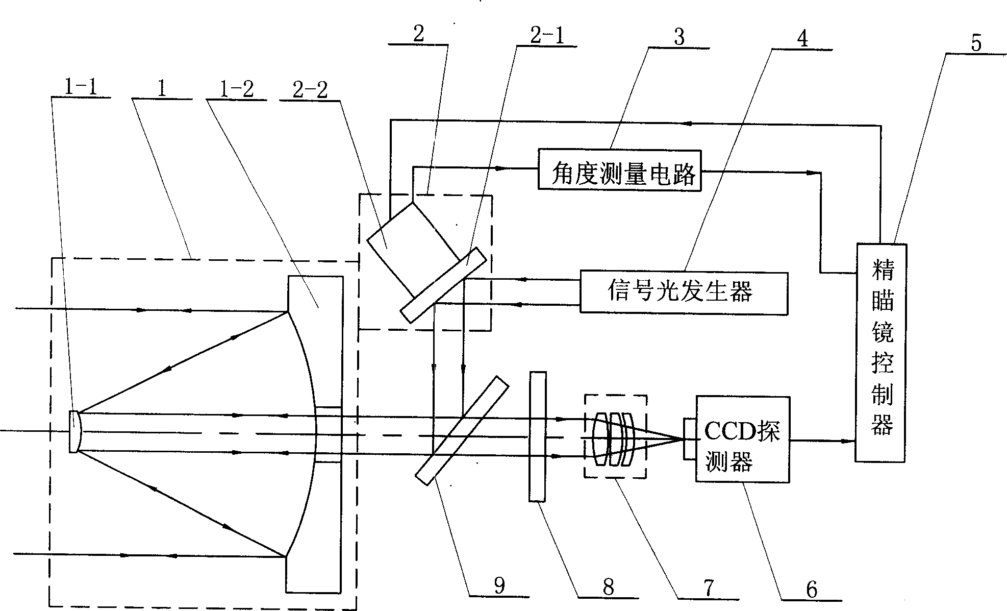
[0008] see figure 1 , the compensation system of this specific embodiment consists of an optical antenna 1, a signal light generator 4, a precise aiming mirror 2, a fine aiming mirror controller 5, a CCD detector 6, an angle measurement circuit 3, and an imaging lens group 7 on a satellite platform , a beam splitter 9 and a filter 8, the beacon light emitted by the target terminal is converted into parallel incident light by the optical antenna 1 and is incident on the light input end of the beam splitter 9, all output from the transmitted light output end of the beam splitter 9 Said parallel incident light is incident on the light input end of imaging lens group 7 after filtering light plate 8, obtains focused beam at the light output end of imaging lens group 7 and forms an image on CCD detector 6, and the output end of CCD detector 6 is connected The image signal input terminal of the fine aiming mirror controller 5; the fine aiming mirror 2 is composed of a total reflectio...


PUM


Abstract

This invention relates to a compound feed back control vibration compensation system based on CCD, in which, the beacon light emitted by a target terminal passes through an optical antenna, a light splitting plate, a filter and an imaging lens set to be imaged on a CCD detector, the signal light output by a signal light generator passes through a total reflection mirror and a light splitting plate to be expanded by the optical antenna and emitted to a target terminal, a precise aiming mirror controller utilizes the CCD detector to get the information of an angle of declination to control the deflection of the total reflection mirror to let signal lights emit to the target terminal along the initial path of the beacon light accurately. The compensation system can detect the vibration of a satellite platform timely.

Description

technical field [0001] The invention relates to the technical field of satellite optical communication. Background technique [0002] The satellite optical communication terminal is carried by the satellite platform, and the vibration of the satellite platform will cause the terminal antenna to deviate, causing the signal light sent by the terminal to deviate from the target optical communication terminal (the ground terminal or the on-board terminal with which the link is established). This situation will attenuate the signal optical power that can be received by the target terminal, and in severe cases, it will cause the interruption of the satellite laser communication link. Therefore, it is one of the key problems in the research of satellite optical communication technology to propose an effective compensation method for satellite platform vibration. At present, my country's satellite optical communication system is in the development stage, and an effective satellite ...

Claims


Application Information

Patent Timeline
IPC IPC(8): H04B10/105H04B10/118
Inventor 谭立英马晶韩琦琦于思源
Owner HARBIN INST OF TECH
Why Eureka
Try Eureka