Block for construction, panel for construction using the block, and method of molding panel for construction

A technology for construction and building blocks, which is applied in the direction of construction, building materials, building components, etc., can solve the problems of weak strength of connecting blocks, deterioration of adhesives, lack of durability, etc., to improve strength and durability, improve insulation Heat resistance, effect of improving durability

Inactive Publication Date: 2006-08-30
TAMA HOME
View PDF0 Cites 3 Cited by
  • Summary
  • Abstract
  • Description
  • Claims
  • Application Information

AI Technical Summary

Problems solved by technology

[0008] The laminated concrete block described in Patent Document 1 can accurately and reliably laminate the blocks by using the connecting pin member, but since the connecting pin member must be arranged on all the boundaries between the adjacent blocks in the vertical direction, Therefore, such an operation requires a lot of labor and time.
[0009] In addition, since these connecting pin members are not members that draw and fix the blocks together, if a tensile force in the axial direction of the connecting pin members is applied to the boundary between the blocks after the laminated construction, there is a possibility that the masonry may be damaged. blocks will separate
Therefore, it is generally suitable for structures such as walls, fences, and foundations that only apply a compressive force in the axial direction of the connecting pin member, and is not suitable for structures that may apply external forces in the deflection direction, such as the floor of a building.
[0010] On the other hand, in the construction method of a block wall described in Patent Document 2, while bonding the joint surfaces of a plurality of concrete blocks arranged vertically and horizontally with an adhesive, inserting and fastening steel rods for tension , to form a flat plate of blocks, but since the insertion of the tension steel rod is the joint part of the adjacent blocks, the strength connecting the blocks to each other is weak
[0011] In addition, because the joint surfaces of the blocks are bonded with an adhesive, the adhesive deteriorates or shrinks after a period of time after construction, and the joint parts of the blocks may be separated or gaps may be formed, resulting in lack of durability. sex

Method used


Image

  • Block for construction, panel for construction using the block, and method of molding panel for construction
  • Block for construction, panel for construction using the block, and method of molding panel for construction
  • Block for construction, panel for construction using the block, and method of molding panel for construction

Examples


Embodiment Construction

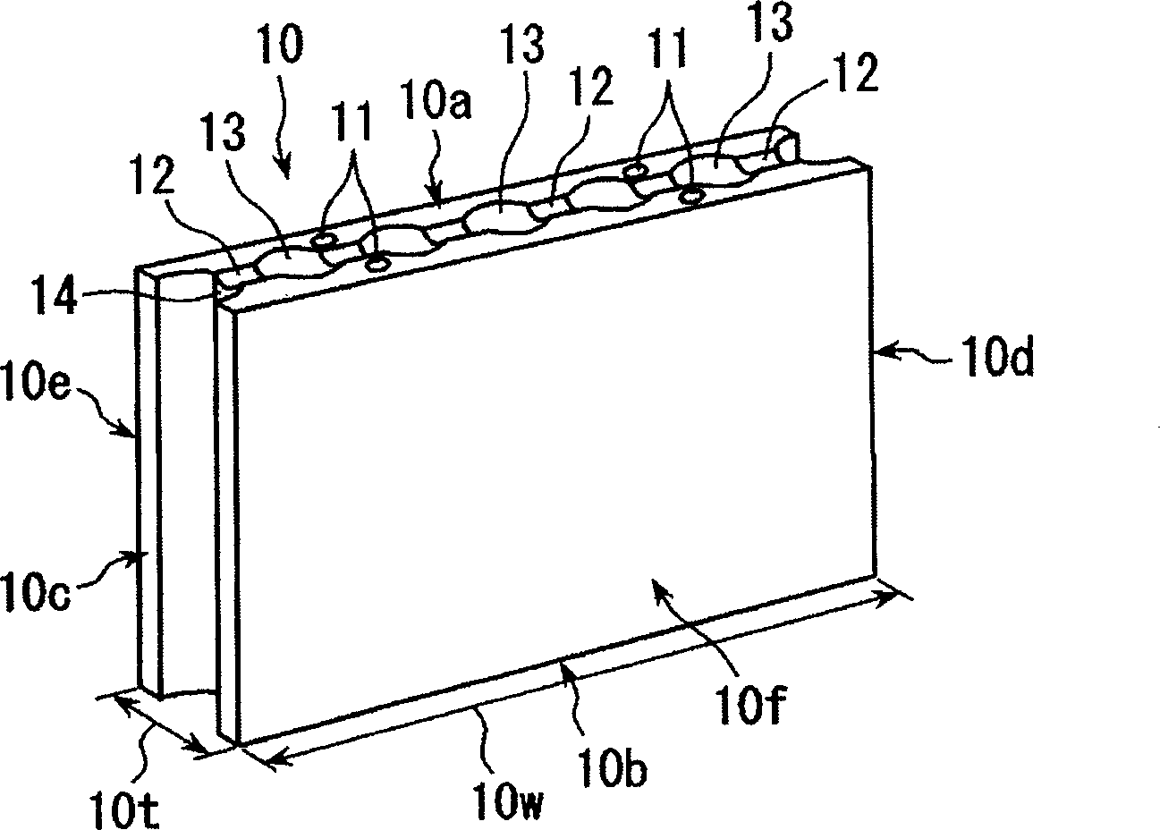
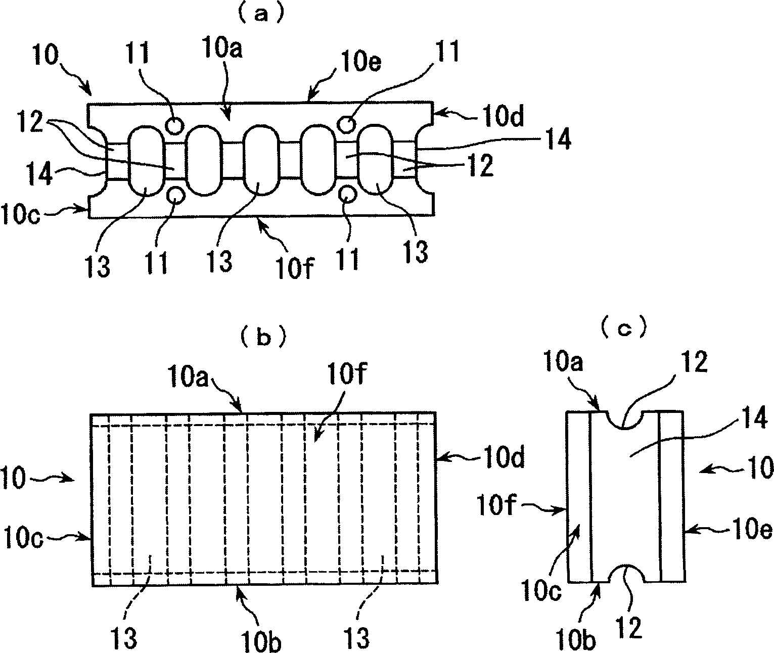
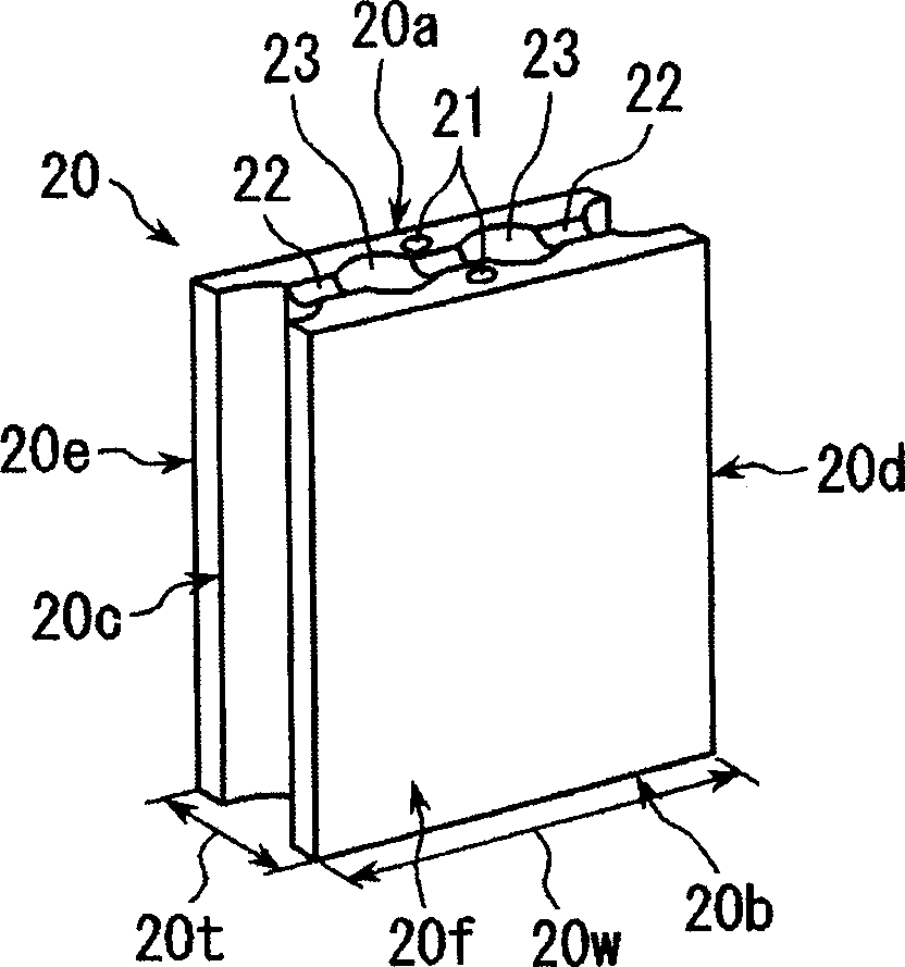
[0073] refer to Figure 1 to Figure 10 , The construction blocks and the construction slabs formed by applying the construction blocks according to the first and second embodiments of the present invention will be described.

[0074] Such as figure 1 , figure 2 As shown, the construction blocks 10 of the first embodiment are arranged in a plurality of planes by making the four outer peripheral surfaces of the upper surface 10a, the lower surface 10b, the left side 10c, and the right side 10d contact each other as will be described later. Blocks that can build planar structures. On building block 10, be formed with its front 10f and back 10e parallel to a plurality of through-holes 11 that are used to insert the rod-shaped tightening parts that will be described later. The other tensioning members are arranged in the direction of the through hole 11, so that the upper surface 10a and the lower surface 10b of the outer peripheral surface intersecting the axial direction of t...


PUM


Abstract

A block (10) for construction capable of constructing a flat structure by arranging the plurality of blocks in a flat state with four outer peripheral surfaces thereof, that are, an upper surface (10a), a lower surface (10b), a left side surface (10c), and a right side surface (10d) brought into contact with each other. In the block (10) for construction, a plurality of through holes (11) for inserting bar-like stretching members therein are formed parallel with the front surface (10f) and the rear surface (10e) thereof, and recessed parts (12) are formed in the upper surface (10a) and lower surface (10b) forming outer peripheral surfaces crossing the axial direction of the through holes (11) to dispose the other stretching members in a direction three-dimensionally crossing the stretching members inserted into the through holes (11). By using the block (10) for construction, the flat structures such as the wall parts and floor parts of a building can be easily constructed in a rather short period, and the durabilities of these flat structures can also be increased.

Description

technical field [0001] The present invention relates to a technique for constructing a planar structure such as a wall portion, a floor portion, or a ceiling portion of a reinforced concrete building. Background technique [0002] Conventionally, when constructing structures such as walls and floors of reinforced concrete buildings, a method of assembling a concrete sand box at a construction site, arranging steel bars in the sand box, and then pouring concrete has been used. [0003] However, this casting-in-place method requires a lot of labor and time in various processes such as assembling the sand box, pouring the concrete, curing and curing the concrete, and thus becomes an obstacle to shortening the construction period. In addition, in each of these steps, specialized skilled workers are required. [0004] In addition, since the loading, assembling and concrete pouring of sand box materials and reinforcing steel materials require a wide work area, the workability is ...

Claims


Application Information

Patent Timeline
Patent Type & Authority Applications(China)
IPC IPC(8): E04C1/00E04C2/38E04C2/40E04B2/02E04B2/14E04B2/26E04C2/04
CPCE04B5/023E04B2/14E04B5/043E04B2/26E04B2002/0254E04C2/041
Inventor 中村光男
Owner TAMA HOME
Why Eureka
Try Eureka