Spraying chamber

A technology of spraying booths and coating booths, applied in the field of spraying booths, which can solve problems such as long distances, large-scale painting booths, poor coating, etc., and achieve the effect of maintaining the coating environment, eliminating troubles, and improving operation interruptions

Inactive Publication Date: 2006-09-13
ANEST IWATA CORP +1
View PDF2 Cites 10 Cited by
  • Summary
  • Abstract
  • Description
  • Claims
  • Application Information

AI Technical Summary

Problems solved by technology

Therefore, it is hoped that the painting room is wide enough, and the distance between the object to be painted and the wall is long, so that the paint mist can be attracted by the exhaust flow before it reaches the wall. However, this will increase the size of the painting room and increase the burden on equipment.
[0015] In the case where the painting room is narrow and the distance between the wall surface and the

Method used


Image

  • Spraying chamber
  • Spraying chamber
  • Spraying chamber

Examples


Embodiment Construction

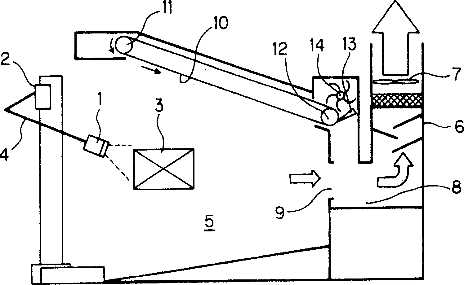
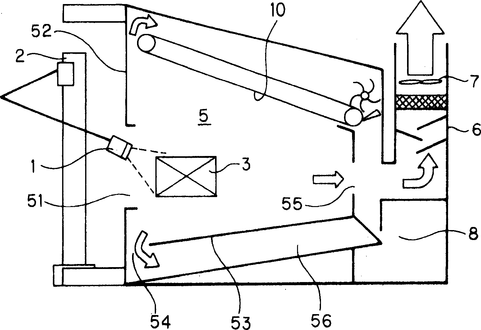
[0037] The specific content when implementing the present invention will be described below with reference to the accompanying drawings. figure 1 It is a schematic configuration diagram showing an example of a painting booth for carrying out the present invention. In this example, the spray gun 1 is an automatic spray gun, and spraying is performed automatically by compressed air, and usually, spraying is controlled by compressed air from a solenoid valve operated by a signal from a control device. The spray gun 1 is mounted on a painting robot 2 as an automatic painting device, and the painting position, direction, etc. are controlled and operated to paint the object 3 to be painted. Usually, the painting robot 2 can not only move up and down, left and right, and front and back by the arm 4, but also can make the spray gun 1 freely carry out the spraying operation by means of the angle change and rotary operation of the installation part of the spray gun 1. The signal of the...


PUM


Abstract

The spray booth has no trouble for the paint attached to the ceiling of the spray booth to fall onto the sprayed article contaminatively and has changeable front opening size for minimized airflow rate for spraying. The spray booth is provided with one rotary filter net, one movable filter net wall near the ceiling for removing the paint attached to the filter net, and one removing device outside the spray booth to operate regularly for removing the attached paint. In addition, the spray booth has one front movable reduced opening, and the opening may be moved and changed in area based on the size and the shape of the sprayed article so as to minimize the airflow rate for spraying.

Description

technical field [0001] The present invention relates to a spray booth for collecting and treating paint mist splashed by spraying during painting. Background technique [0002] The spray booth (hereinafter referred to as the coating booth) is used to attract and capture the paint mist that has not adhered to the object to be coated with the spray, so as to prevent it from adhering to the object to be coated again, and is used to reduce An indispensable device for the discharge of harmful substances that adversely affect the surrounding environment including paint mist. The paint particles sprayed in the painting room that are not attached to the object to be painted are attracted by the airflow toward the exhaust gas treatment device, but it cannot be avoided due to the direction of the spray, the turbulent flow of the airflow, or the position of the wall surface that the airflow contacts, etc. attached to the interior wall. [0003] The attached paint is used for a long t...

Claims


Application Information

Patent Timeline
IPC IPC(8): B05B15/12B05C11/10B05B13/04B05B15/04
Inventor 白岩充弘二宫诚堂木藤信雄谷川原季宏木村泰吉田满年
Owner ANEST IWATA CORP
Why Eureka
Try Eureka