Rubber base and manufacturing method thereof

A rubber bearing and rubber technology, which is applied in the direction of building components, shock absorbers, and shockproof, can solve the problems of prone to partial steel plates, poor support flatness, and easy to have partial plates on steel plates, etc., to achieve reliable process assurance, flatness, etc. Good degree and uniform exhaust effect

Active Publication Date: 2006-09-13
柳州东方工程橡胶制品有限公司
View PDF0 Cites 12 Cited by
  • Summary
  • Abstract
  • Description
  • Claims
  • Application Information

AI Technical Summary

Problems solved by technology

[0002] Existing rubber bearings are generally composed of steel plates and elastic rubber bodies. The outer surface of the general elastic rubber body is flat, but the flatness of this type of support is poor, and the inner steel plate is likely to have a partial plate. The elastic rubber body and The contact of the reinforced steel plate is not close enough. This is because the glue removal and exhaust are carried out around the upper and lower mold covers of the mold during the manufacturing process of the original rubber bearing. Due to the single method of glue removal and exhaust, the exhaust effect Not very good, so the flatness of the support is poor. If the gap between the upper and lower mold covers is large and the positioning is not good, the rubber material cannot be discharged evenly, which will cause a large height difference in the support product and prone to partial plate phenomenon; It will be more difficult to meet the flatness requirements when producing large or extra large bearing products

Method used


Image

  • Rubber base and manufacturing method thereof
  • Rubber base and manufacturing method thereof
  • Rubber base and manufacturing method thereof

Examples


Embodiment 1

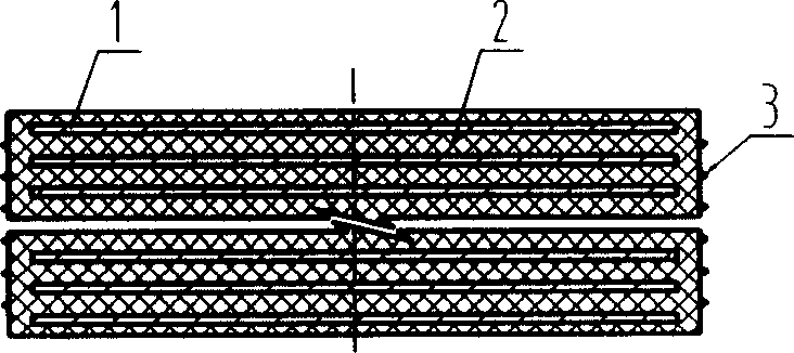
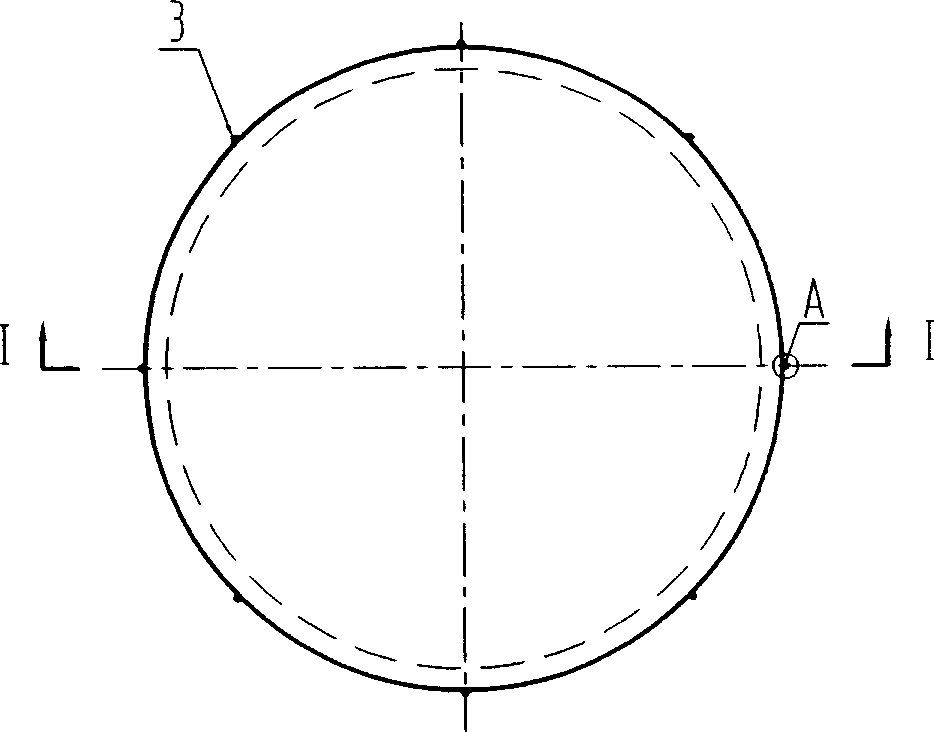
[0038] Embodiment 1: A cylindrical rubber bearing, which is a cylinder-shaped bearing formed by sequentially laminating M layers of rubber and M-1 layers of stiffened steel plates and vulcanized, including stiffened steel plates 1, elastic rubber vulcanized into one Body 2, there is a protective rubber layer on the side of the support, and there are N evenly distributed small protrusions 3 on the surface of the protective rubber layer on the longitudinal side of the support. The shape of the small protrusions 3 is a combination of a hemisphere and a cylinder Body shape (referring to Fig. 9), its maximum diameter is 0.1~10mm, length is 1~100mm, the value range of M, N is: M=2~10, N=10~200.

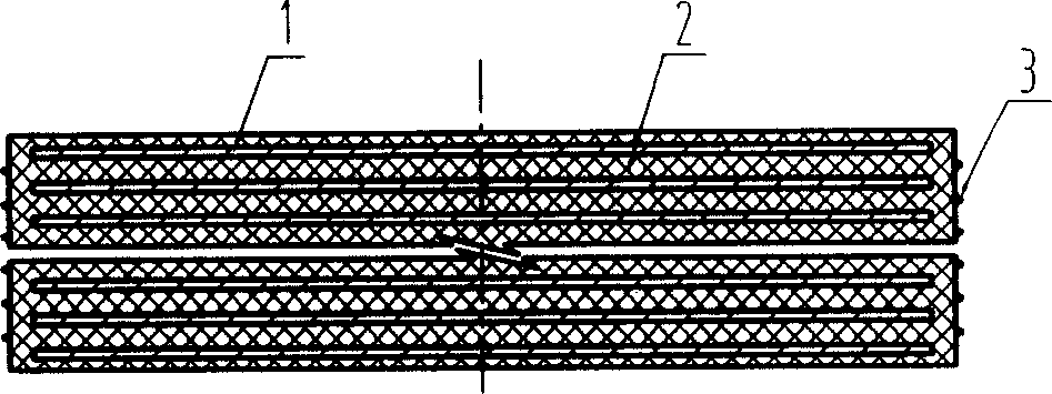
[0039] As a transformation of Embodiment 1 of the present invention, the shape of the rubber support can also be a cuboid or a cube (see image 3 , Figure 4 ), the shape of the small protrusion on it also can be the combination shape (referring to Fig. 10) of conical body and cylinder.

Embodiment 2

[0040] Embodiment two: a kind of square rubber bearing (referring to Figure 5 , Figure 6 ), which is a square support formed by vulcanizing successive lamination of M layer rubber, M-1 layer stiffening steel plate and connecting steel plates on the upper and lower bottom surfaces, including stiffening steel plate 1 and elastic rubber body 2 vulcanized into one, located on the upper , the upper and lower connecting steel plates 5 on the lower bottom surface 1 , there are 4 through holes in the middle of the support, and there are 4 high-purity lead cores in the holes. 1 , there are protective rubber layers on the four longitudinal sides of the support, and there are N evenly distributed small protrusions 3 on the surface of the protective rubber layer on the longitudinal sides of the support. The maximum diameter is 0.1-10mm, the length is 1-100mm, and the value ranges of M and N are: M=2-10, N=10-200.

Embodiment 3

[0041] Embodiment three: a kind of square rubber bearing (referring to Figure 7 , Figure 8 ), which is a cube support formed by sequentially laminating and vulcanizing the M layer of rubber, the M-1 layer of stiffening steel plate and the connecting steel plates on the upper and lower bottom surfaces, including the stiffening steel plate 1 and the elastic rubber body 2 vulcanized into one, located on the upper and lower The upper and lower connecting steel plates 5 on the lower bottom surface 2 , there is a through hole in the middle of the support, and a high-purity lead core 4 is placed in the hole 2 There are protective rubber layers on the four longitudinal sides of the support, and there are N evenly distributed small protrusions 3 on the surface of the protective rubber layer on the longitudinal sides of the support. The shape of the small protrusions 3 is cylindrical (see Figure 17), The maximum diameter is 0.1-10mm, the length is 1-100mm, and the value ranges of M ...


PUM

PropertyMeasurementUnit
lengthaaaaaaaaaa

Abstract

The invention relates to a rubber bracket and the manufacturing method thereof, where the rubber bracket is of a cuboid, or cylinder or other geometrical shape formed of multiple layers of elastic rubber and multiple layers of reinforced steel plates by in turn laminating and sulfuration, the vertical side surface of the rubber bracket has a protective rubber layer with 1-1500 uniformly distributed small bumps, the shape of the bump is a cylinder, or cuboid or circular truncated cone or their combined body, and the manufacturing method comprises the steps of stock preparing, mould processing, mould splicing, mould assembling, vulcanizing, demoulding, etc, where a side mould has N air and glue discharge holes and the shape of the side mould is that one end is big and the other end is small, where the big end is located at the inner wall of the side mould and the small end is externally made with glue discharge groove connected with the atmosphere, the air and glue discharge can be performed on the side surface of the mould, and the air discharge is uniform to make upper and lower covers tightly contact with the side mould, and the rubber bracket has good planeness, accurate height but no inclined plates in the steel plates.

Description

Technical field: [0001] The invention relates to a vibration damping device and a manufacturing method thereof, in particular to a rubber bearing and a manufacturing method thereof. Background technique: [0002] Existing rubber bearings are generally composed of steel plates and elastic rubber bodies. The outer surface of the general elastic rubber body is flat, but the flatness of this type of support is poor, and the inner steel plate is likely to have a partial plate. The elastic rubber body and The contact of the reinforced steel plate is not close enough. This is because the glue removal and exhaust are carried out around the upper and lower mold covers of the mold during the manufacturing process of the original rubber bearing. Due to the single method of glue removal and exhaust, the exhaust effect Not very good, so the flatness of the support is poor. If the gap between the upper and lower mold covers is large and the positioning is not good, the rubber material can...

Claims


Application Information

Patent Timeline
Patent Type & Authority Applications(China)
IPC IPC(8): F16F7/00E01D19/04E04B1/98B29C35/00
Inventor 资道铭周大庆黄光宇庞军莫志严陈胜腾刘志东
Owner 柳州东方工程橡胶制品有限公司
Why Eureka
Try Eureka