

Magnetic vortex street flowmeter
A vortex flowmeter, electromagnetic technology, applied in the field of flowmeter, can solve the problems of high production cost, affecting the measurement result, affecting the normal generation of eddy current, etc., and achieve the effect of reducing production cost and accurate small flow rate
- Summary
- Abstract
- Description
- Claims
- Application Information
AI Technical Summary
Problems solved by technology
Method used
Image

Examples
Embodiment
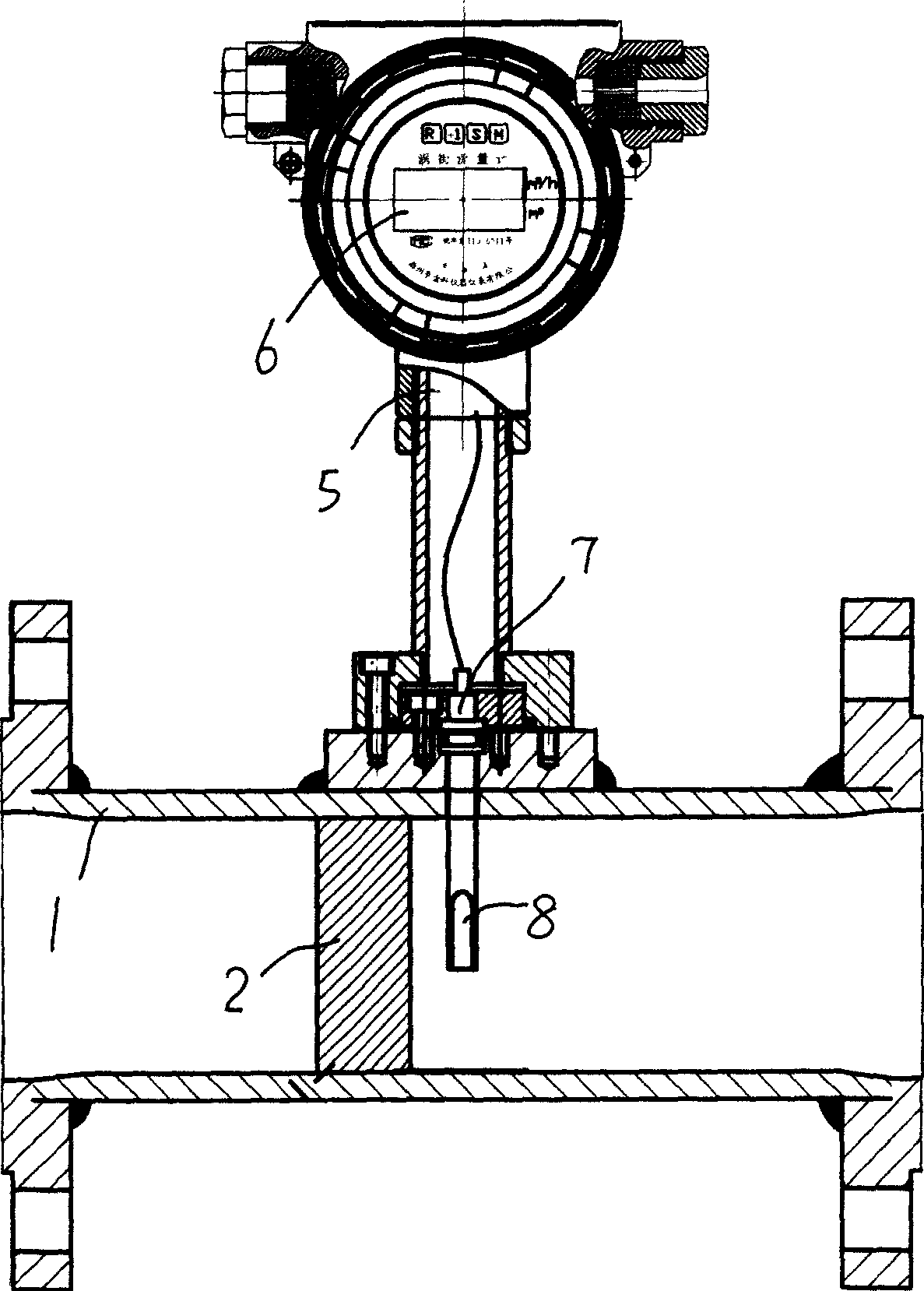
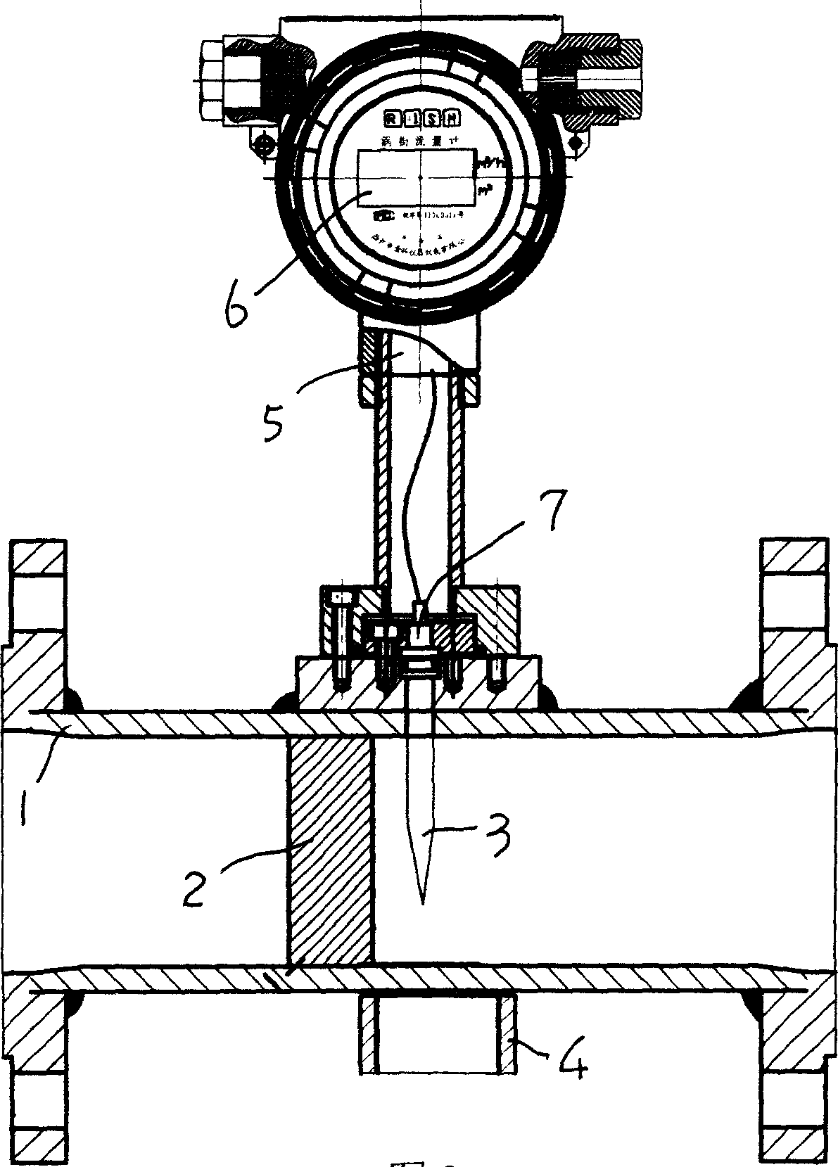
[0021] see figure 2 , image 3 , in the flow tube 1, set the triangular column 2 as usual, set the probe 3 on the back of the triangular column 2, set the permanent magnet 4 outside the flow tube 1 corresponding to the position of the probe 3, and use the probe 3 and the permanent magnet 4 constitute a signal sensor.
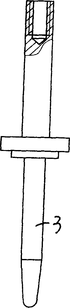
[0022] In specific implementation, the probe 3 is a needle-shaped conductor, suspended vertically in the center of the flow tube 1, the tail of the probe 3 is placed outside the flow tube 1, and connected to the terminal 7 by threads, and the detection signal is in the terminal 7 lead out.
[0023] According to the principle of Karman vortex street, when there is fluid flowing through the flow tube 1, due to the existence of the triangular column 2, resistance will be generated to divert the fluid, so an eddy current will be generated in front of the probe 3; at the same time, due to the permanent magnet 4 at this position If it exists, a strong magnetic fie...
PUM
 Abstract
Description
Claims
Application Information