Battery and method of manufacturing the same

A manufacturing method and battery technology, which are applied to battery pack components, circuits, electrical components, etc., can solve the problems of increased internal resistance of the battery, reduced charge and discharge current values, and complicated lead wires, so as to suppress the decrease in current value and facilitate easy assembly. Effect

Inactive Publication Date: 2006-09-13
SANYO ELECTRIC CO LTD
View PDF1 Cites 19 Cited by
  • Summary
  • Abstract
  • Description
  • Claims
  • Application Information

AI Technical Summary

Problems solved by technology

However, in the conventional battery described above, since the lead wire 155 and the sealing plate 153 need to be welded with the sealing plate 153 tilted (that is, the opening surface of the outer packaging can 151 and the sealing plate 153 are kept approximately perpendicular to each other), therefore The lead wire 155 electrically conducted with the electrode body 154 becomes long, and when the thickness of the lead wire 155 becomes large, it becomes difficult to weld, so the cross-sectional area of ​​the lead wire 155 cannot be increased.
Due to these factors, the internal resistance of the battery increases when outputting a large current, and there is a problem that the current value during charge and discharge decreases.
[0009] In addition, in the process of caulking and fixing the sealing plate 153 to the opening of the outer can 151 , in order to store the sealing plate 153 inside the outer can 151 , a complicated work of bending the lead wire 155 is required.

Method used


Image

  • Battery and method of manufacturing the same
  • Battery and method of manufacturing the same
  • Battery and method of manufacturing the same

Examples


Embodiment approach 2

[0090] Hereinafter, Embodiment 2 of the present invention will be specifically described with reference to the drawings. In addition, the same reference numerals are used for members having the same functions as in the first embodiment, and descriptions thereof are omitted.

[0091] The battery capacity of the lithium-ion secondary battery of mode 2 is about 5Ah, and the structure of the negative electrode collector plate 2, the positive electrode collector plate 4, and the sealing plate 5 is different. are the same, so only the differences will be described below.

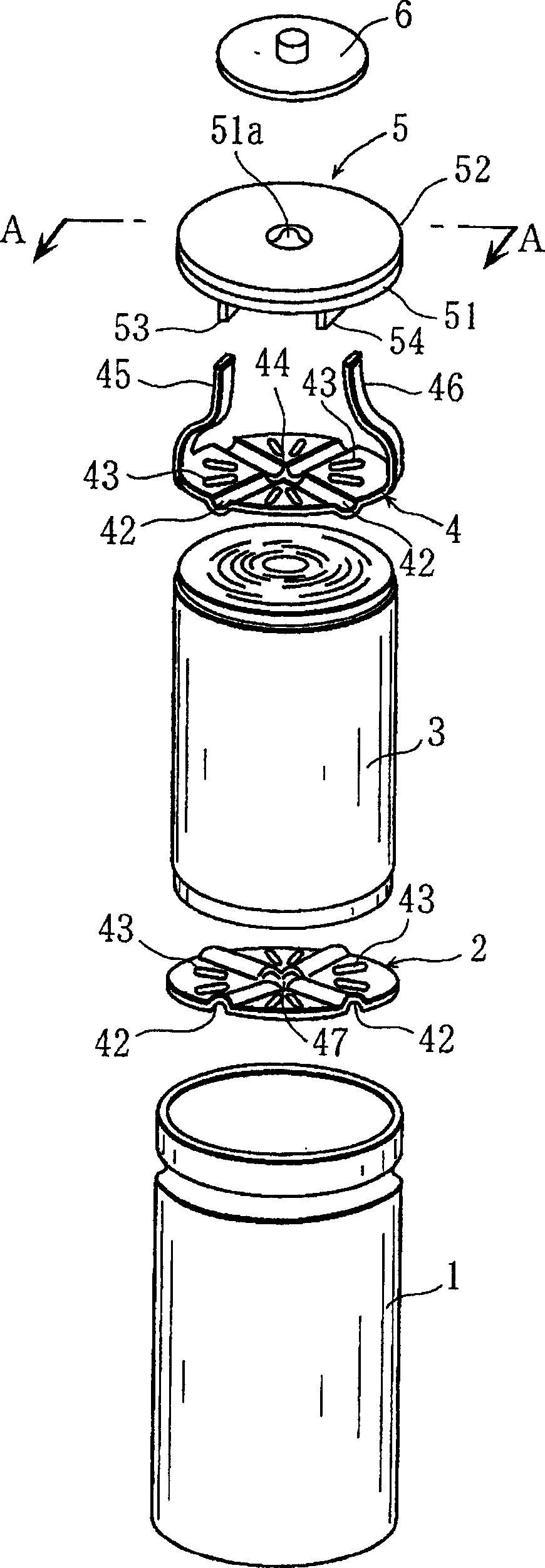
[0092] The positive collector plate 4 is as Figure 10 As shown in FIG. 15 (a) (b), since a part of the positive electrode current collector plate 4 is rolled up substantially perpendicular to its surface to form a plate-shaped lead 45, it is not extended from the end of the positive electrode current collector plate 4. The lead wire 45 is different from Embodiment 1 in that only one lead wire 45 is provided and...

no. 1 Embodiment

[0106] (Example)

[0107] As an example, the lithium ion secondary battery shown in Embodiment 1 was used.

[0108] Hereinafter, the battery produced in this way will be referred to as the battery A of the present invention.

no. 2 Embodiment

[0119] (Example)

[0120] As an example, the lithium ion secondary battery shown in Embodiment 2 was used.

[0121] Hereinafter, the battery produced in this way is referred to as the battery B of the present invention.

[0122] (comparative example)

[0123] As a comparative example, the lead length is 30 mm, the lead width is 15 mm, the lead thickness is 0.5 mm, and the battery capacity is about 5.0 Ah, except that it has the same structure as the comparative example of the first embodiment. Furthermore, the difference in lead wire length and the like from the comparative example of the first embodiment is due to the difference in battery capacity.

[0124] Hereinafter, the battery produced in this way is referred to as a comparative battery Y.

[0125] (experiment)

[0126] Table 2 shows the results of measuring the electrical resistivity of the battery B at a frequency of 1 kHz for the battery B of the present invention and the comparative battery Y.

[0127] ...


PUM

PropertyMeasurementUnit
diameteraaaaaaaaaa
thicknessaaaaaaaaaa
lengthaaaaaaaaaa

Abstract

PROBLEM TO BE SOLVED: To provide a cylinder-shaped secondary battery, capable of easily connecting a current collector plate to a sealing plate and reducing internal resistance, and to provide a manufacturing method of the same.SOLUTION: The cylinder-shaped secondary battery is constituted by storing an electrode body 2, impregnated with nonaqueous electrolyte in a battery can 10 formed by fixing a sealing plate 4 to the opening of a bottomed cylindrical body 11. A pair of electrodes 21, 22 are made to protrude at both end parts of the electrode body 2, disc-shaped first and second current collector plates 31, 32 are connected to the end part of both electrodes 21, 22 respectively; and the surface of the second current collector plate 32 is resistance-welded to a bottom face of the bottomed cylindrical body 11. A plate-shaped projection piece 33, extending from the surface of the first current collector plate 31 toward the sealing plate 4 is protrusively arranged on the first current collector plate. A slit 41, into which the protrusion piece 33 is to be inserted, is opened at a position corresponding to the position of the protrusion piece 33, and laser welding is applied to a part where the projection piece 33 is fitted to the slit 41.

Description

technical field [0001] The present invention relates to a battery in which an electrode body serving as a power generation element is accommodated in an outer can and electric energy generated by the electrode body can be output from a positive electrode terminal portion and a negative electrode terminal portion to the outside, and a method for manufacturing the same. Background technique [0002] In recent years, not only electronic devices such as mobile phones, personal computers, and PDAs, but also electric tools, power-assisted bicycles, and electric vehicles have begun to demand batteries capable of outputting large currents for driving motors (high-output batteries). As a current collecting structure of such a high output battery, a so-called jointless structure in which circular current collecting plates are welded to the upper and lower ends of a cylindrically wound electrode body is generally used. As a battery having such a structure, there is, for example, a batt...

Claims


Application Information

Patent Timeline
Patent Type & Authority Applications(China)
IPC IPC(8): H01M2/04H01M2/26H01M50/152H01M50/179H01M50/188H01M50/528
CPCY02E60/122Y02E60/12Y02E60/10
Inventor 佐藤广一大北一成横山智彦池町隆明
Owner SANYO ELECTRIC CO LTD
Why Eureka
Try Eureka