
Conservative force motor

A technology of engines and conservative forces, applied in electromechanical devices, electric components, control mechanical energy, etc., can solve problems such as lack of practicality, and achieve the effects of improving feasibility, saving energy, and reducing environmental pollution

Inactive Publication Date: 2006-09-13
孟武
View PDF5 Cites 0 Cited by
  • Summary
  • Abstract
  • Description
  • Claims
  • Application Information

AI Technical Summary

Problems solved by technology

[0003] In the above-mentioned many designs, most of the basic characteristics of the conservative force are ignored. For example, in "Permanent Magnet Power Machine", it is said that "at least one is a special unipolar permanent magnet". At present, no magnetic monopole has been found in the world. It is not easy, the characteristics that can be clarified by simple experiments such as the difficulty of separating the two opposite magnetic poles after attracting each other; as for the elastic force, if it is used alone, it is even less practical

Method used


Image

  • Conservative force motor
  • Conservative force motor
  • Conservative force motor

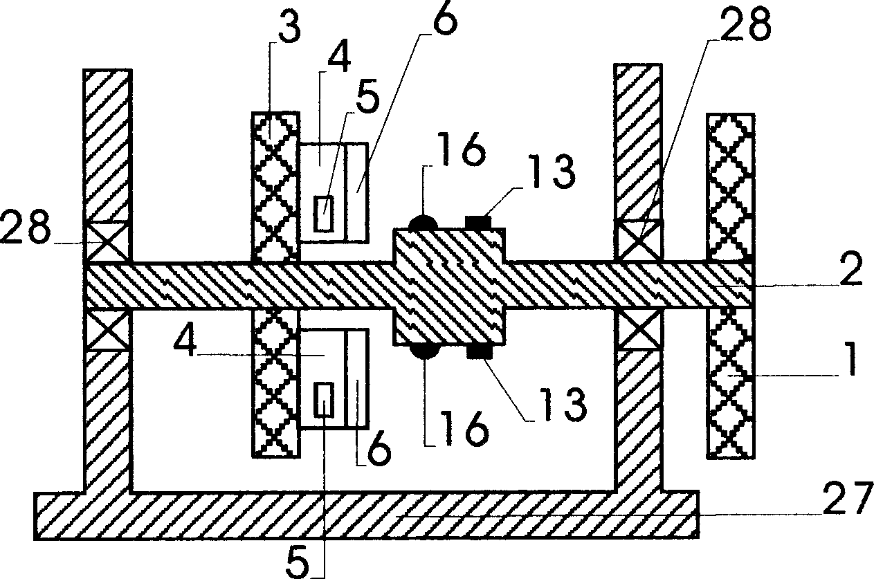
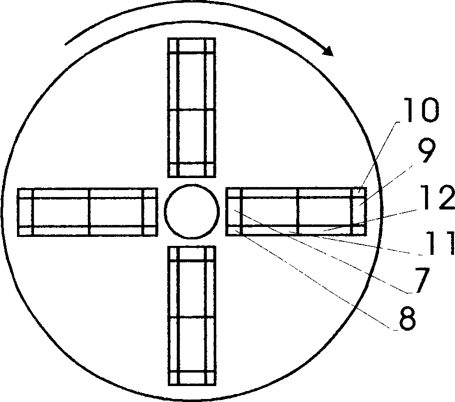
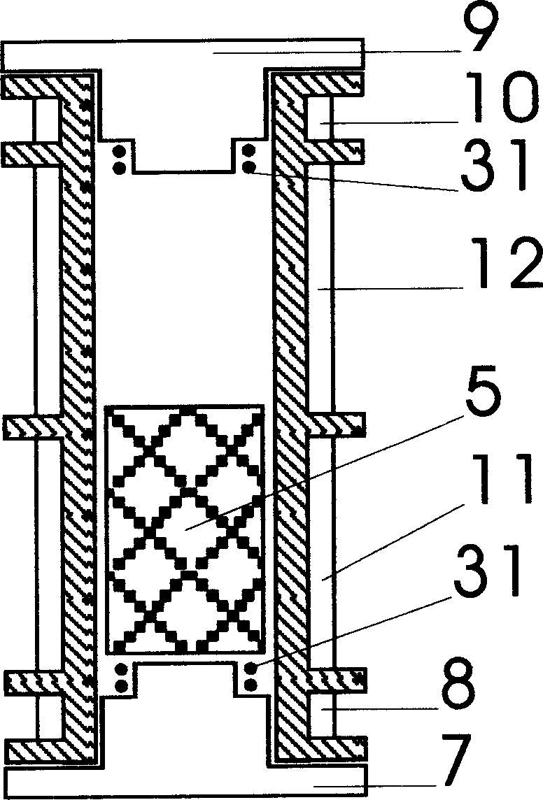
Examples


Embodiment Construction

[0023] The present invention is described in detail below in conjunction with accompanying drawing:

[0024] See Figure 1 to Figure 4 , on the bracket 27, the gravity shaft 2 is erected by two bearings 28, one end of the gravity shaft 2 is connected with an output power disc 1, and the power is output outwards, and at least one gravity disc 3 is connected at the middle part of the gravity shaft, and the gravity disc 3, at least a pair of gravity cylinders 4 are installed with the gravity axis as the center. Gravity bodies 5 are installed in the gravity cylinders 4. According to the difference of gravity bodies 5, different anti-gravity systems 6 are selected to be installed. Driven by the anti-gravity system 6, The gravity body 5 moves to the near-axis side when the gravity cylinder 4 turns up, and moves to the far-axis side under the action of centrifugal force when it turns down, so that the gravity disc 3 generates a gravity moment and makes the gravity work continuously. ...


PUM


Abstract

This invention provides a conservative engine applying the combination of gravity, static magnetic field and static electric field characterizing in fixing at least a gravity plate on a gravity shaft connected with an output power plate and fixing at least a pair of gravity cylinders on the plate with the shaft as the center, in which, the gravity body in the cylinder moves to the near shaft side when rotating to the lowest point and to the far shaft side when moving to the highest point so that the gravity plate generates a moment to work continuously.

Description

technical field [0001] The invention relates to an engine, in particular to a conservative force engine which organically combines gravity, static electricity and static magnetism to form a power source. Background technique [0002] As we all know, gravity, elastic force, static electricity, and static magnetism are collectively called conservative forces, and their characteristic is that their work along the closed path is zero. In view of the two major themes of energy and environmental protection, people have done a lot of exploration and research on whether conservative forces can do work. The Chinese invention patent "Permanent Magnet Power Machine" (Patent No. 97101394.2) published on October 15, 1997 has two power plates, and the opposite surfaces of the two plates have permanent magnets with the same polarity and repelling each other, at least one of which is a special The unipolar permanent magnet has a two-pole gap guarantee mechanism, and the magnetic component ...

Claims


Application Information

Patent Timeline
IPC IPC(8): H02K53/00H02K7/02
CPCY02E60/16
Inventor 孟武
Owner 孟武
Learn More