
Circuit arrangement for cooling charge air and method for operating a circuit arrangement of this type

A supercharged air and circuit technology, which is applied in the direction of engine cooling, coolant flow control, and liquid cooling.

Inactive Publication Date: 2006-09-13
BEHR GMBH & CO KG
View PDF0 Cites 12 Cited by
  • Summary
  • Abstract
  • Description
  • Claims
  • Application Information

AI Technical Summary

Problems solved by technology

[0004] If the engine efficiency is to be continuously improved, the above-mentioned known supercharging systems are limited in their supercharging coefficient and operating parameter characteristics under low load conditions

Method used


Image

  • Circuit arrangement for cooling charge air and method for operating a circuit arrangement of this type
  • Circuit arrangement for cooling charge air and method for operating a circuit arrangement of this type
  • Circuit arrangement for cooling charge air and method for operating a circuit arrangement of this type

Examples


Embodiment Construction

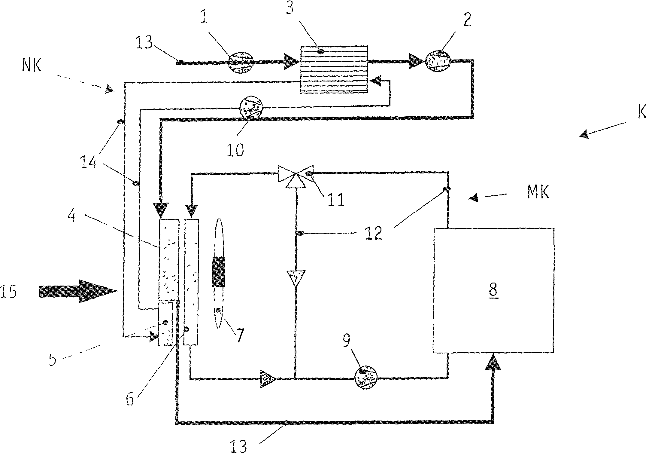
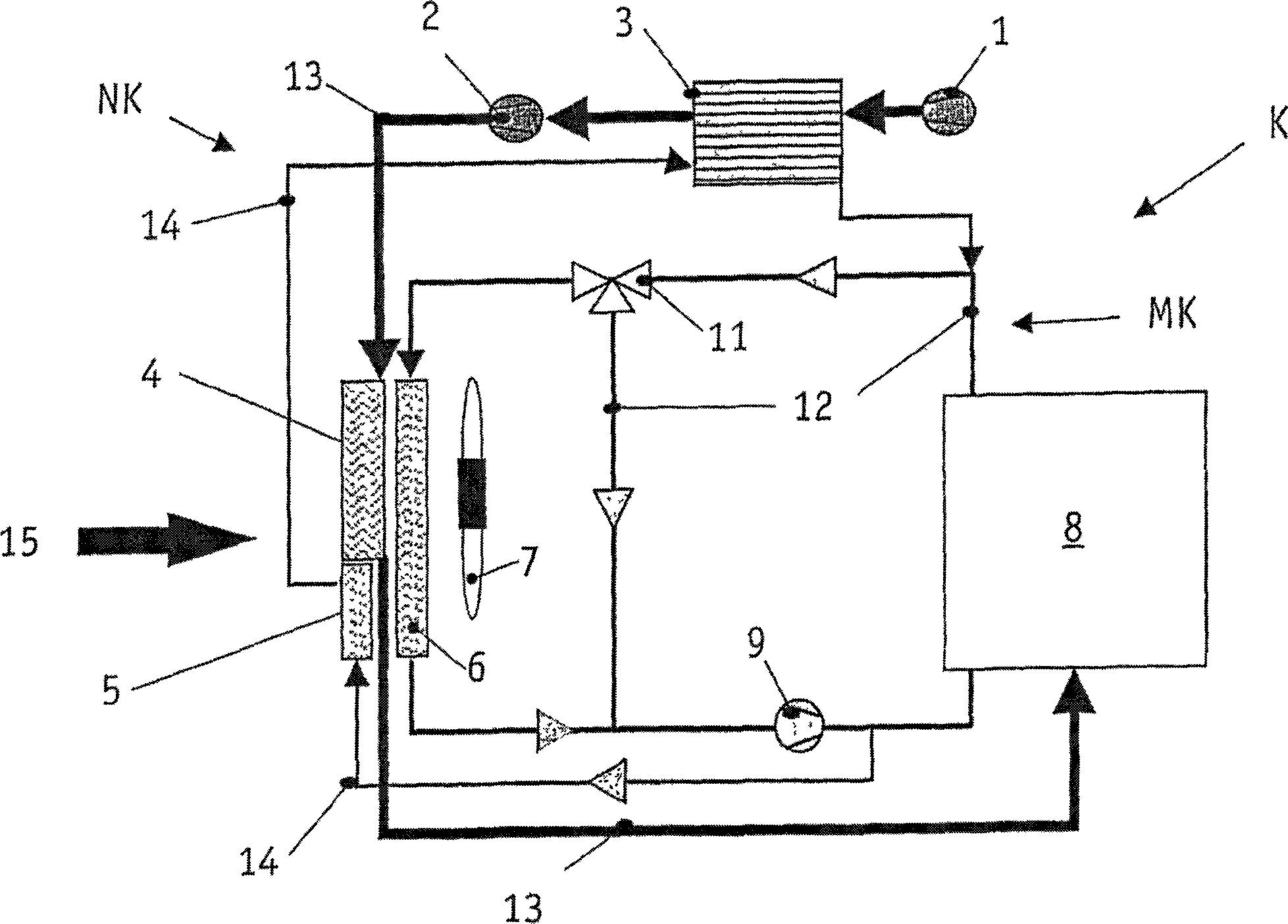
[0017] figure 1 In is a circuit arrangement for cooling two turbochargers connected in series, namely a low-pressure turbocharger 1 and a high-pressure turbocharger 2 . Reference numeral 13 refers to charge air, which is sucked in from the surrounding environment and compressed in the first stage in the low-pressure turbocharger 1 . During this process, the temperature of the charge air 13 increases. In order to continue the compression and at the same time avoid the overheating of the components that are in direct or indirect contact with the charge air 13 and cause the life to be affected Cooling in a low-pressure charge air / coolant cooler 3 which is part of the low-temperature circuit NK. The low temperature circuit NK will be described in detail later.

[0018] After being cooled by the low-pressure-charge air / coolant-cooler 3, the charge air 13 enters the high-pressure-turbocharger 2, where it is further compressed to its final pressure, during which The air is heated...


PUM


Abstract

The invention relates to a circuit arrangement (K) comprising a low-temperature circuit (NK) for cooling charge air (13) that is fed to a motor (8) in a motor vehicle equipped with a turbocharger. According to the invention, the charge air (13) is compressed in two stages in a first low-pressure turbocharger (1) and a second high-pressure turbocharger (2). To cool the charge air (13) a first cooler (3) is provided downstream of the low-pressure turbocharger (1) and upstream of the high-pressure turbocharger (2) and a second cooler (4) is provided downstream of the high-pressure turbocharger (2) and upstream of the motor (8). The invention also relates to a method for operating a circuit arrangement (K) of this type.

Description

technical field [0001] The invention relates to a charge air cooling circuit arrangement for use in a motor vehicle equipped with a turbocharger according to the preamble of claim 1 and to a method of operating such a circuit arrangement. Background technique [0002] According to the prior art, in order to increase the efficiency of the engine, turbochargers are used in automobiles to increase the air consumption in the engine. During the compression required for this, the air (called charge air below) heats up due to the compression in the turbocharger. To compensate for the pressure loss due to the heating of the charge air, that is to say the increased air density, a gas cooler is used which is arranged in the front cooling module and cools the charge air. The charge air is passed through a heat exchanger, and the ambient air is also passed through the heat exchanger and cools it. In this way, the charge air can be cooled to a temperature approximately 15K higher than ...

Claims


Application Information

Patent Timeline
Patent Type & Authority Applications(China)
IPC IPC(8): F02B29/04F02B37/013F01P3/18F01P5/10F01P7/16
CPCY02T10/146F02B29/0443F01P2003/185F02B37/013F01P2003/187F02B29/0412F02B29/0431F01P2005/105Y02T10/144F01P2060/02F01P7/165F02B29/0475F01P2003/182Y02T10/12
Inventor 斯特凡·罗吉安妮格雷·蒂尔曼
Owner BEHR GMBH & CO KG
Learn More