Gas cooking stove
A technology of gas stoves and stoves, which can be used in household stoves, heating fuels, household appliances, etc., and can solve problems such as covering and difficulty in confirming firepower
- Summary
- Abstract
- Description
- Claims
- Application Information
AI Technical Summary
Problems solved by technology
Method used
Image

Examples
Embodiment 1
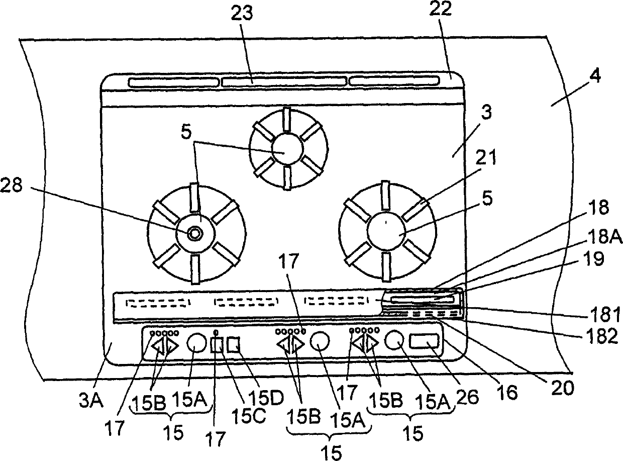
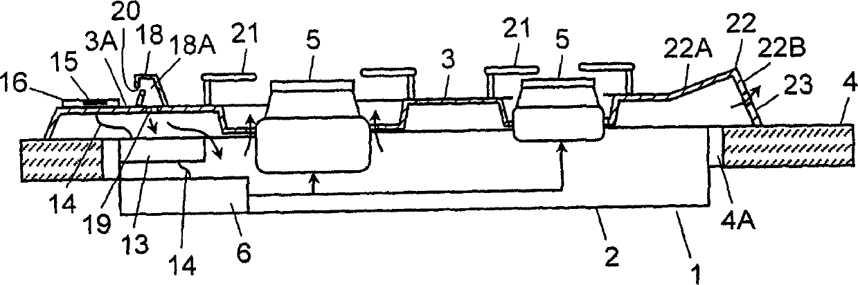
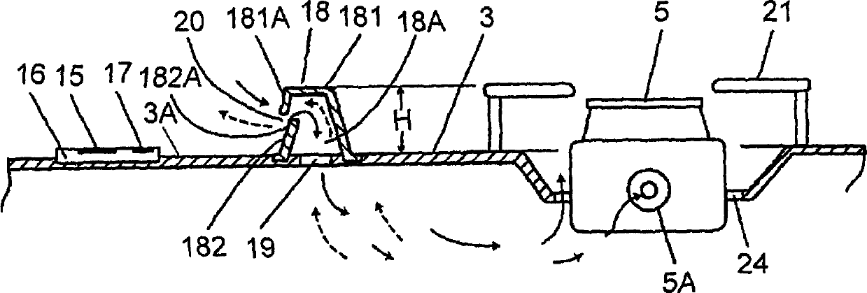
[0046] Fig. 1 and Fig. 2 are a top view and a schematic sectional view of main parts of a gas cooker embedded in kitchen furniture according to Embodiment 1 of the present invention. Fig. 3A is an enlarged cross-sectional view of the vicinity of a partition wall of the gas cooker in Fig. 2 . Fig. 4 is a block diagram of the gas flow control section.
[0047] A cooker body 1 as a device body is composed of a box-shaped casing 2 and a top plate 3 covering the upper part. Then, the cooker main body 1 is fitted into the opening 4A of the cooktop 4 constituting the kitchen furniture, and the outer peripheral edge of the top plate 3 is placed on the upper surface of the peripheral edge of the opening 4A.
[0048] The three burners 5 that use gas as fuel are partly located in the housing 2 and face the top plate 3 without protruding high. side. A gas flow control device (hereinafter referred to as a control unit) 6 is connected to the burner 5 through piping, and the control unit ...
Embodiment 2
[0100] Fig. 7 and Fig. 8 are a perspective view and a top view of a gas cooker built into kitchen furniture according to Embodiment 2 of the present invention. Fig. 9 is a schematic sectional view of the gas cooker, and Fig. 10 is a block diagram of a gas flow control section.
[0101] In this embodiment, in order to avoid the influence of heat from the burner 5 , the operating part 15 on the top plate 3 has a step relative to the upper surface of the top plate 3 , or is set to incline downward toward the front side of the cooker body 1 . The following description will focus on the points different from the first embodiment.
[0102] In the gas cooker of this embodiment, the arrangement and structure of the operation portion 15 indicating combustion control etc. on the top plate 3 are not controlled by the burner 5 or the gas flow control device (hereinafter referred to as the control unit) 6 in the housing 2. The constraints of the arrangement of the part 13 can obtain the s...
Embodiment 3
[0150] Fig. 17 and Fig. 18 are a top view and a schematic sectional view of the main part of the gas cooker embedded in the kitchen furniture of the third embodiment. Fig. 19 is an enlarged sectional view of a temperature detector mounting portion. Fig. 20 is a block diagram of a gas flow control section.
[0151] In the gas cooker of the present embodiment, the temperature near the operation part 15 is detected by the temperature detector 52 . When the temperature detector 52 detects a predetermined temperature that affects the operation unit 15 by heat, the control unit 13 controls the gas flow control device (hereinafter referred to as a control unit) 6 to reduce the thermal power of the burner 5 . The following description will focus on the points different from the first embodiment.
[0152] In this gas cooker, the arrangement and structure on the top plate 3 of the operation part 15 for instructing combustion control, etc., are not affected by the combustion control part...
PUM
 Abstract
Description
Claims
Application Information
 - R&D
- Intellectual Property
- Life Sciences
- Materials
- Tech Scout
- Unparalleled Data Quality
- Higher Quality Content
- 60% Fewer Hallucinations
Browse by: Latest US Patents, China's latest patents, Technical Efficacy Thesaurus, Application Domain, Technology Topic, Popular Technical Reports.
© 2025 PatSnap. All rights reserved.Legal|Privacy policy|Modern Slavery Act Transparency Statement|Sitemap|About US| Contact US: help@patsnap.com