Gas valve device and gas stove
A technology of gas valve and gas, applied in the direction of valve device, valve operation/release device, valve details, etc., can solve the problems of increasing manufacturing cost, reducing service life, hidden safety hazards, etc., to improve the degree of intelligent control and reduce safety The effect of reducing hidden dangers and reducing mechanical wear
- Summary
- Abstract
- Description
- Claims
- Application Information
AI Technical Summary
Problems solved by technology
Method used
Image

Examples
Embodiment 1
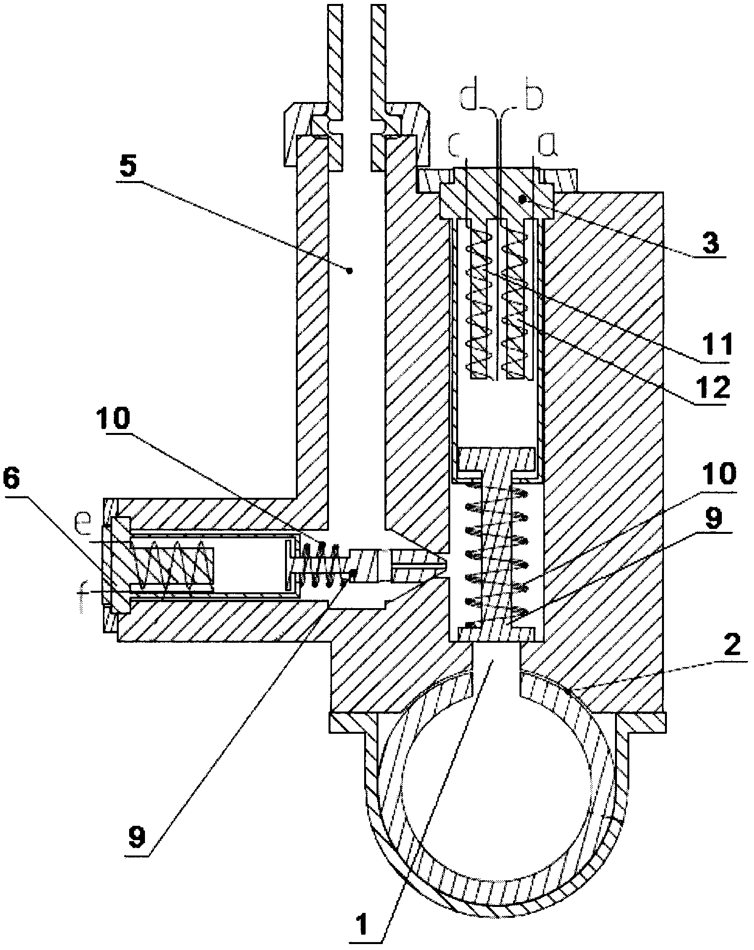
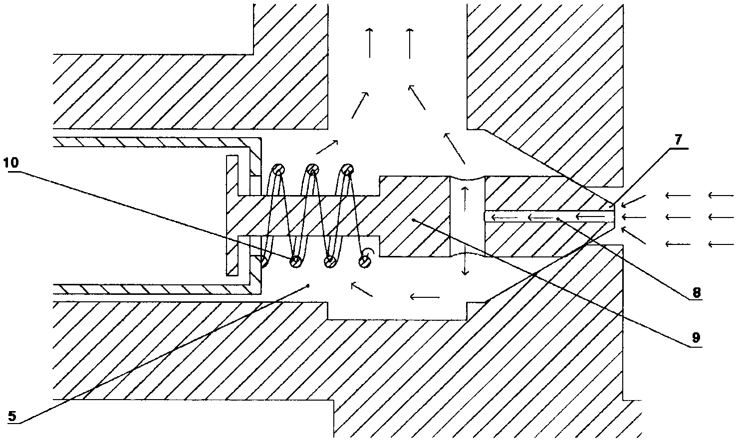
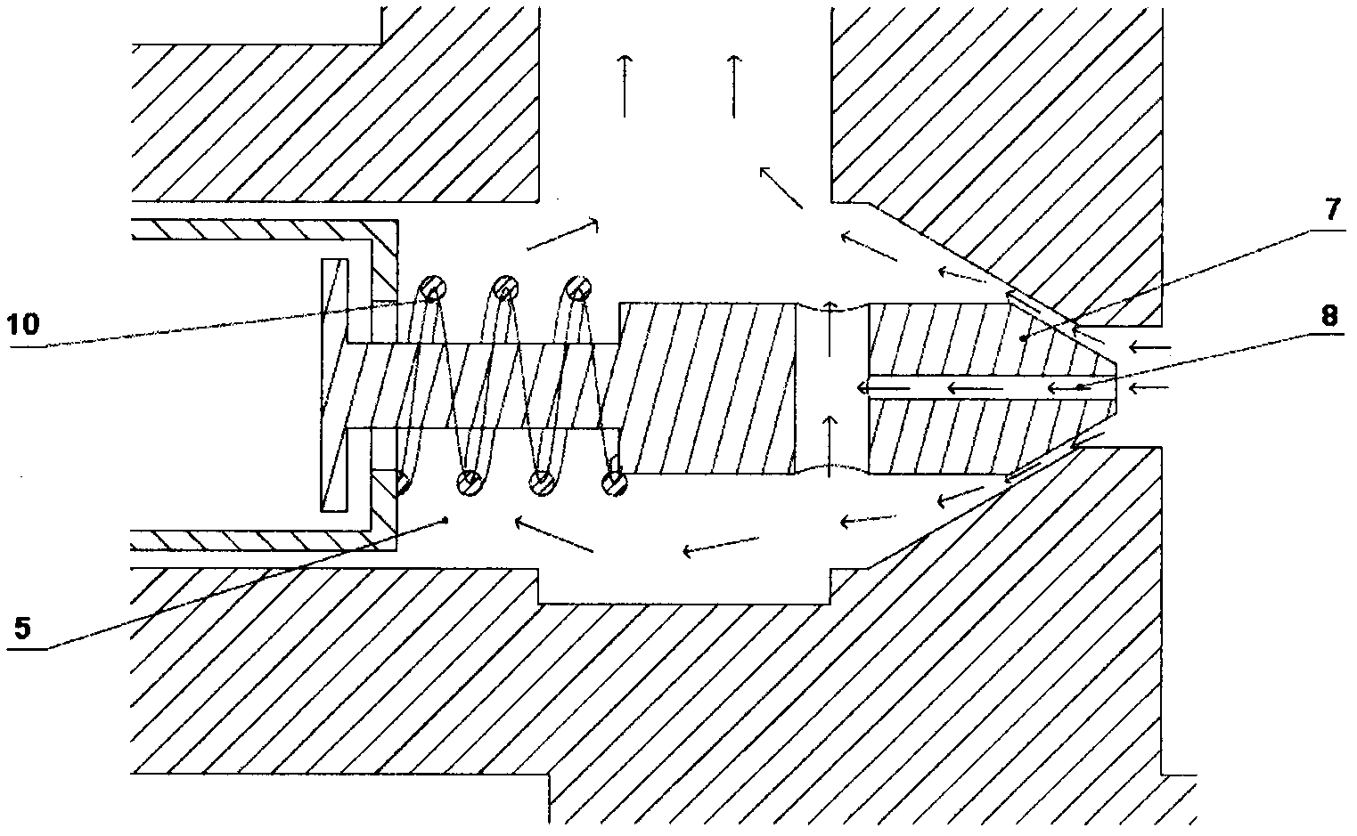
[0029] Such as Figures 1 to 4 As shown, the present invention provides a gas valve device. The gas valve device includes a gas inlet 1, a main control solenoid valve 3, a first gas mixing chamber 5, a control module 4, and a first solenoid valve 6 arranged between the main control solenoid valve 3 and the first gas mixing chamber 5, The gas inlet 1 communicates with the main gas pipe 2 . The first air mixing chamber 5 is used to supply air to the burner. Specifically, the first gas mixing chamber 5 delivers the gas to the Venturi mixing tube, and the Venturi mixing tube mixes the gas with air and then transmits it to the burner. The control module 4 is used for controlling the main control solenoid valve 3 and the first solenoid valve 6 .
[0030] When the main control solenoid valve 3 is opened, gas flows to the first solenoid valve 6 through the main control solenoid valve 3; when the main control solenoid valve 3 is closed, gas cannot flow to the first solenoid valve 6 ...
Embodiment 2
[0036] This embodiment is improved on the basis of Embodiment 1. Compared with Embodiment 1, this embodiment adds a second air-mixing chamber 14 and a second solenoid valve 15 arranged between the main control solenoid valve 3 and the second air-mixing chamber 14 . The first air mixing chamber 5 is used to supply air to the central small flame cover of the burner. The second air mixing chamber 14 is used to supply air to the outer ring fire cover of the burner. When the main control solenoid valve 3 is opened, gas flows to the second solenoid valve 15 through the main control solenoid valve 3; when the main control solenoid valve 3 is closed, gas cannot flow to the second solenoid valve 15 through the main control solenoid valve 3. The second solenoid valve 15 is used to control whether the gas flowing through the main control solenoid valve 3 flows to the second gas mixing chamber 14 and the flow rate. The control module 4 is also used to control the second solenoid valve 1...
Embodiment 3
[0040] This embodiment is improved on the basis of Embodiment 1. The main control solenoid valve in this embodiment includes a valve core, a spring and an electromagnet. The electromagnetic coil of the electromagnet is connected with the thermocouple, and the electromagnetic coil of the electromagnet is also connected with the control module. That is to say, the electromagnetic coil of the electromagnet is connected with the thermocouple and the control module at the same time. The control module is used to control the magnitude and direction and duration of the current flowing to the electromagnetic coil of the electromagnet. The spool is magnetic and fixed magnetically. Because the control module can control the flow direction of the current flowing to the electromagnetic coil of the electromagnet, the magnetism of the electromagnet can be changed, which can generate attraction to the spool and repulsion to the spool. Furthermore, this embodiment can also conveniently rea...
PUM
 Abstract
Description
Claims
Application Information
 - R&D
- Intellectual Property
- Life Sciences
- Materials
- Tech Scout
- Unparalleled Data Quality
- Higher Quality Content
- 60% Fewer Hallucinations
Browse by: Latest US Patents, China's latest patents, Technical Efficacy Thesaurus, Application Domain, Technology Topic, Popular Technical Reports.
© 2025 PatSnap. All rights reserved.Legal|Privacy policy|Modern Slavery Act Transparency Statement|Sitemap|About US| Contact US: help@patsnap.com