Heat recovery system of gas cooker

A technology of heat recovery and gas stoves, which is applied in household heating, heating methods, water heaters/stoves, etc., can solve the problems of non-energy-saving hot water heating methods, high production costs of hot water, and waste of heat, and achieve heat recovery Ideal effect, low production cost, and improved comfort

Inactive Publication Date: 2011-06-22
苏宇贵
View PDF3 Cites 13 Cited by
  • Summary
  • Abstract
  • Description
  • Claims
  • Application Information

AI Technical Summary

Problems solved by technology

[0003] The reason is that there are obvious defects in the current domestic hot water heating methods, and most of the hot water heating methods are not energy-saving, and the production cost of hot water is too high. , Most of the daily life still uses cold water. In fact, in winter, a large amount of cold water is used in family life.
[0004] On the other hand, a large amount of heat in family life is wasted, and further improvement is needed in realizing energy conservation and environmental protection.

Method used


Image

  • Heat recovery system of gas cooker
  • Heat recovery system of gas cooker
  • Heat recovery system of gas cooker

Examples


Embodiment 1

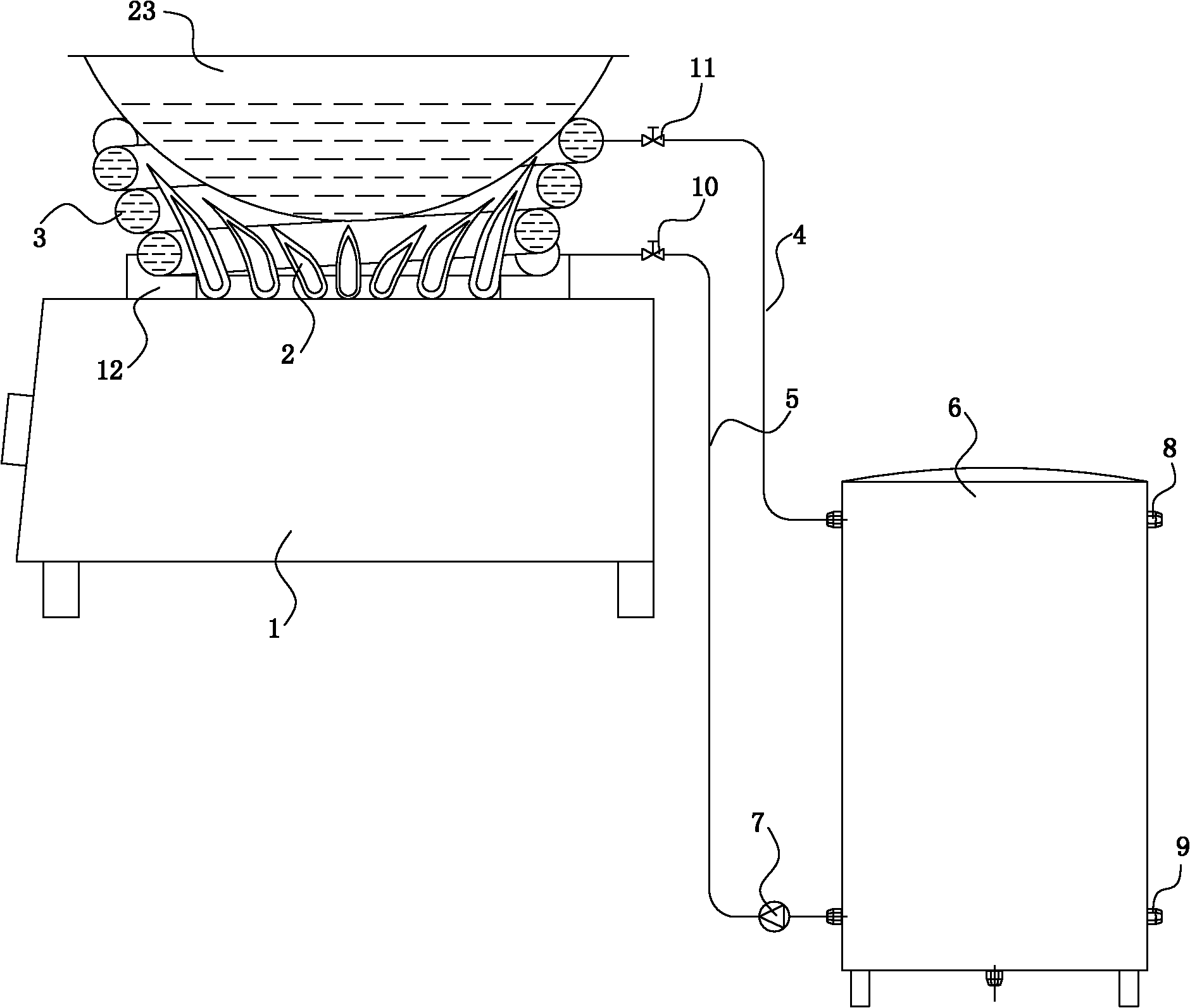
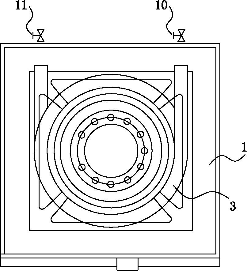
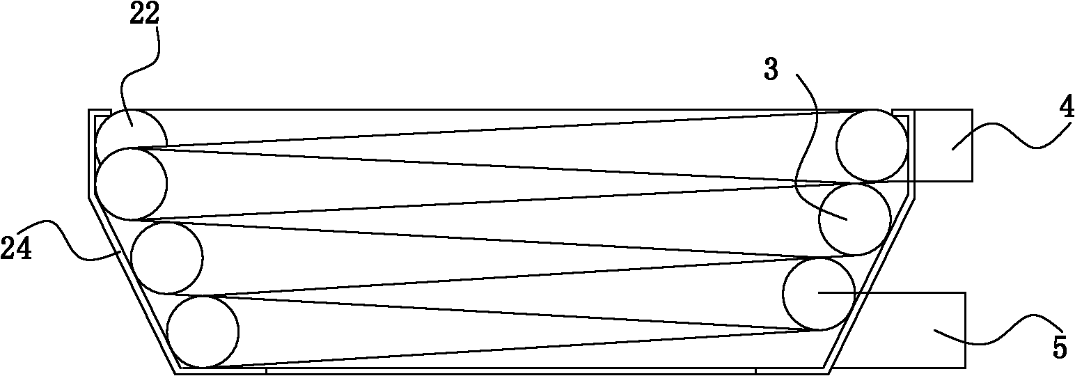
[0028] Example as figure 1 , figure 2 and image 3 As shown, a gas stove heat recovery system includes a gas stove 1, a fire outlet 2 is arranged above the gas stove 1, a cooker 23 is placed above the fire outlet 2, and a heat recovery heat exchanger 3, hot water The outlet pipe 4, the return pipe 5 and the hot water storage tank 6, the heat recovery heat exchanger 3 is arranged around the fire outlet 2, and the two ends of the heat recovery heat exchanger 3 pass through the hot water outlet pipe 4, the return water pipe 5 and the storage tank respectively. The hot water tanks 6 are connected to form a heat recovery pipeline, and a water pump 7 , a hot water outlet 8 and a water replenishment port 9 are arranged on the heat recovery pipeline. The water pump 7 is arranged on the return pipe 5, and the hot water outlet 8 and the replenishment port 9 are arranged on the hot water storage tank 6; There is a water outlet valve 11 on it. A pan support 12 is provided around the ...

Embodiment 2

[0033] Example two such as Figure 4 As shown, in this embodiment, an electric heater 13 is also provided in the hot water storage tank 6. If the heat recovered from the gas stove 1 is insufficient, the electric heater 13 can be used for auxiliary heating.

Embodiment 3

[0034] Embodiment three such as Figure 5 As shown, in this embodiment, a compressor 14, an evaporator 16, a condenser 15, a throttling element 17 and a four-way valve 18 are also included, the condenser 15 is a water side heat exchanger, the compressor 14, the evaporator 16 , the throttling element 17, the four-way valve 18 and the heat exchange working medium side of the condenser 15 are connected through the heat exchange working medium connecting pipe 19 to form a heat exchange working medium circulation loop, and the water side of the condenser 15 is connected to the heat exchange working medium through the connecting water pipe 20 The recovery pipeline is connected, and a solenoid valve 21 is provided on the connecting water pipe 20 . Compared with the second embodiment, in this embodiment, if the heat recovered from the gas stove 1 is not enough, the compressor 14 can be started for auxiliary heating.


PUM


Abstract

The invention discloses a heat recovery system of a gas cooker, comprising the gas cooker, a heat recovery exchanger, a hot water outlet pipe, a water return pipe and a hot water storage tank. A fire hole is arranged above the gas cooker, the heat recovery exchanger is arranged at the periphery of the fire hole, two ends of the heat recovery exchanger are communicated with the hot water storage tank respectively through the hot water outlet pipe and the water return pipe to form a heat recovery pipeline, and a water pump, a water feeding hole and a hot water outlet are arranged on the heat recovery pipeline. By virtue of the heat recovery system of the gas cooker, heat energy in a home can be recycled, more hot water can be provided for home life, and the comfortableness of the home life is further improved.

Description

technical field [0001] The invention relates to a gas stove heat recovery system. Background technique [0002] In developed countries such as Europe and the United States, the ratio of cold water and hot water use in households reaches 1:9. Cold water is generally only used for flushing toilets and car washing, while hot water is used for other aspects, such as bathing, washing face, washing hands, foot massage, and washing. Dishes, washing dishes, washing clothes, etc., have raised people's lives to a higher level, and fully feel the comfort and convenience of life; in my country, the ratio of cold water to hot water in the family is about 9:1, and life The demand for hot water in the country has not been fully met. [0003] The reason is that there are obvious defects in the current domestic hot water heating methods, and most of the hot water heating methods are not energy-saving, and the production cost of hot water is too high. , Most of the daily life still uses cold ...

Claims


Application Information

Patent Timeline
Patent Type & Authority Applications(China)
IPC IPC(8): F24C13/00
Inventor 苏宇贵
Owner 苏宇贵
Why Eureka
Try Eureka