New energy heat supply floor heat preservation equipment based on energy-saving residence

A new energy and residential technology, applied in the field of new energy heating floor insulation equipment, to achieve the effect of improving heating effect, improving environmental protection and energy saving, and improving utilization efficiency

Pending Publication Date: 2021-07-02
SUNYOUNG CONSTR GROUP
View PDF0 Cites 0 Cited by
  • Summary
  • Abstract
  • Description
  • Claims
  • Application Information

AI Technical Summary

Problems solved by technology

[0004] The purpose of the present invention is to provide a new energy heating floor insulation equipment based on energy-saving residential buildings, to solve the related problems raised in the above-mentioned background technology

Method used


Image

  • New energy heat supply floor heat preservation equipment based on energy-saving residence
  • New energy heat supply floor heat preservation equipment based on energy-saving residence
  • New energy heat supply floor heat preservation equipment based on energy-saving residence

Examples


Embodiment 1

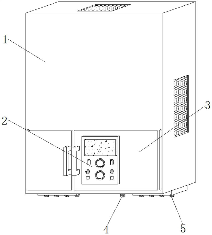
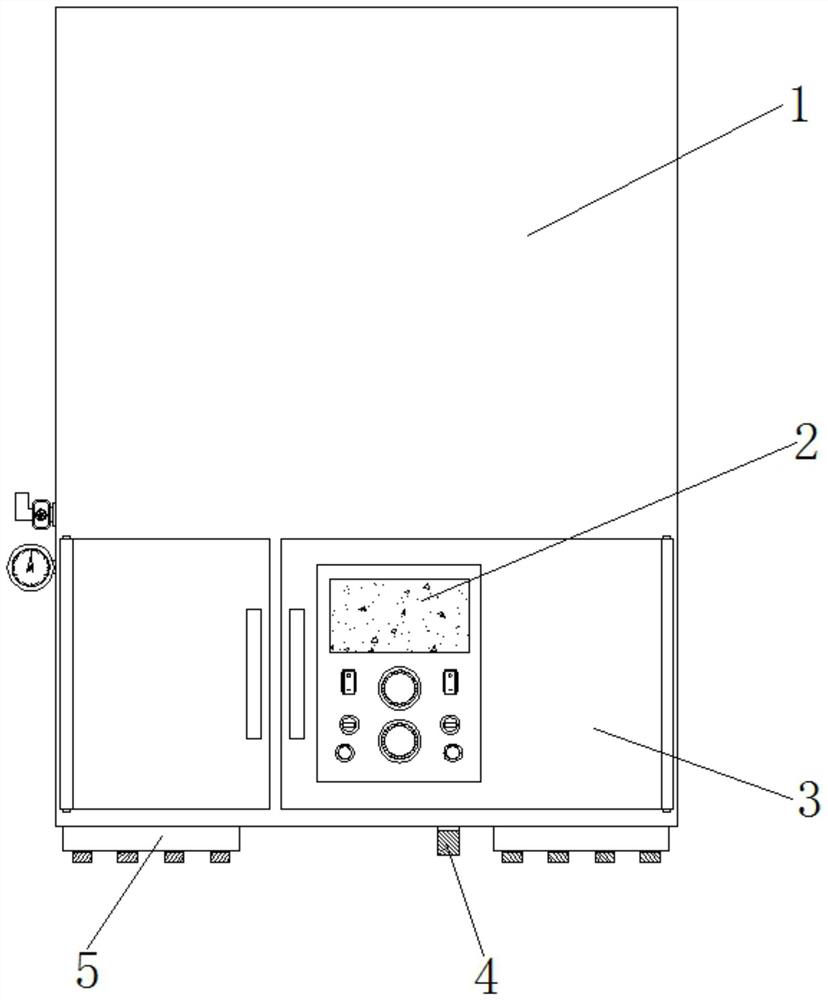
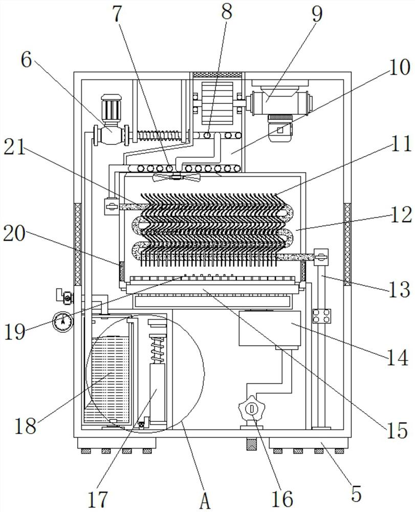
[0038] Example 1, such as Figure 1-7 As shown, when it is necessary to heat the floor and the ground, the ignition electrode 19 is first controlled by the control panel 2 to ignite the gas ejected from the burner 15, and the ignited flame heats the heat conducting sheet 11 and the third heat exchange tube 21, While the flame is heating, the hot air generated by the flame will also flow upwards in the gaps between multiple groups of heat conducting fins 11, and then flow into the inside of the air guiding chamber 10. When the hot air enters the air guiding chamber 10, The liquid inside the first heat exchange tube 7 is heated, and then the liquid inside the second heat exchange tube 8 is heated, and then the fan 9 is used to accelerate the air to be discharged from the top of the air guide chamber 10 in the external environment. Heating the liquid inside the second heat exchange tube 8 plays a preliminary preheating effect, and heating the liquid inside the first heat exchange...

Embodiment 2

[0039] Example 2, such as Figure 1-7 As shown, if the pressure inside the collecting box 18 and inside the heating pipe increases due to liquid heating, the user can see the pressure inside the collecting box 18 through the pressure gauge, and when the pressure reaches the fixed value of the pressure relief valve, The pressure relief valve is opened to reduce the pressure inside the collection box 18, and when the pressure relief valve cannot be opened in time to release the pressure due to a fault, due to the increase in the internal pressure of the collection box 18, the piston 175 will be pushed up inside the collection box 186, and the spring 173 will be pressed. The force stretches and stores the elastic potential energy, and after the top plate 172 is pressed to the touch sensor 171, the touch sensor 171 transmits a signal to the control panel 2, and the control panel 2 controls the solenoid valve 16 to close, thereby stopping the burner 15 from continuously burning the ...


PUM


Abstract

The invention discloses a new energy heat supply floor heat preservation equipment based on the energy-saving house. The new energy heat supply floor heat preservation equipment comprises a main body bin, a heating bin is installed in the middle position of the interior of the main body bin, an air guide bin is installed at the top of the heating bin, a second heat exchange pipe is installed in the middle position of the interior of the air guide bin, a first heat exchange pipe is installed at the inner bottom of the air guide bin, and the ends, located in the center position, of the first heat exchange pipe and the second heat exchange pipe communicate with each other. According to the new energy heat supply floor heat preservation equipment, through cooperative use of heat-conducting fins, an electronic proportional gas valve, a combustor and a third heat exchange pipe, high-temperature air generated by combustion flows upwards between the two adjacent heat-conducting fins, hot air is in continuous contact with the surfaces of the heat-conducting fins in the process, and therefore, the temperature in the air can be greatly transferred to liquid inside the third heat exchange pipe through the heat-conducting fins, the heating effect of the whole new energy heat supply floor heat preservation equipment is improved, and the utilization effect of heat generated by gas combustion is also improved.

Description

technical field [0001] The invention relates to the technical field of heating and heat preservation equipment, in particular to a new energy heating floor heat preservation equipment based on energy-saving houses. Background technique [0002] With the development of science and technology, people are paying more and more attention to the protection of the environment while improving the quality of life. Taking winter heating as an example, compared with coal-fired heating equipment, it will produce more smoke and polluting gases (such as CO2, SO2 etc.) will cause great harm to the environment. Gas heating water heaters use natural gas as energy to heat water through the combustion of natural gas to meet heating needs. Gas heating water heaters are more environmentally friendly and can avoid damage to the environment. pollute. [0003] When the front floor insulation equipment is in use, it usually heats the heat exchanger to heat the flowing water in it, and the heating f...

Claims


Application Information

Patent Timeline
Patent Type & Authority Applications(China)
IPC IPC(8): F24D3/14F24H9/00F24H9/18F23J15/06
CPCF23J15/06F24D3/14F24H9/0005F24H9/1836Y02E20/30
Inventor 胡维腾余昶赵强王红磊雷建石保亮
Owner SUNYOUNG CONSTR GROUP
Why Eureka
Try Eureka