Longitudinal repulsion strong magnetic turn-over bed hinge
A magnetic, plank bed technology, applied to beds, other seating furniture, furniture connections, etc., can solve the problems of spring fatigue, short service life, piston wear, etc., to achieve opening and closing effort, long service life, simple and reasonable structure Effect
- Summary
- Abstract
- Description
- Claims
- Application Information
AI Technical Summary
Problems solved by technology
Method used
Image

Examples
Embodiment 1
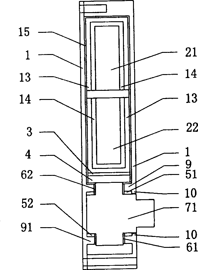
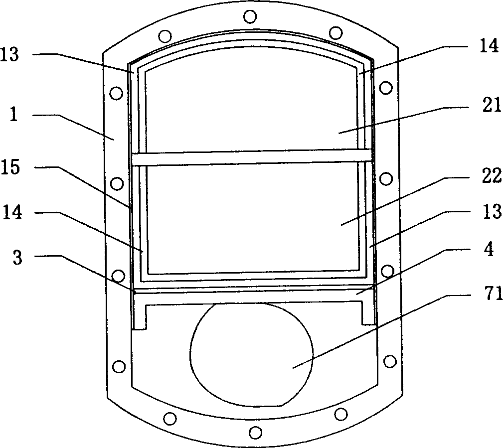
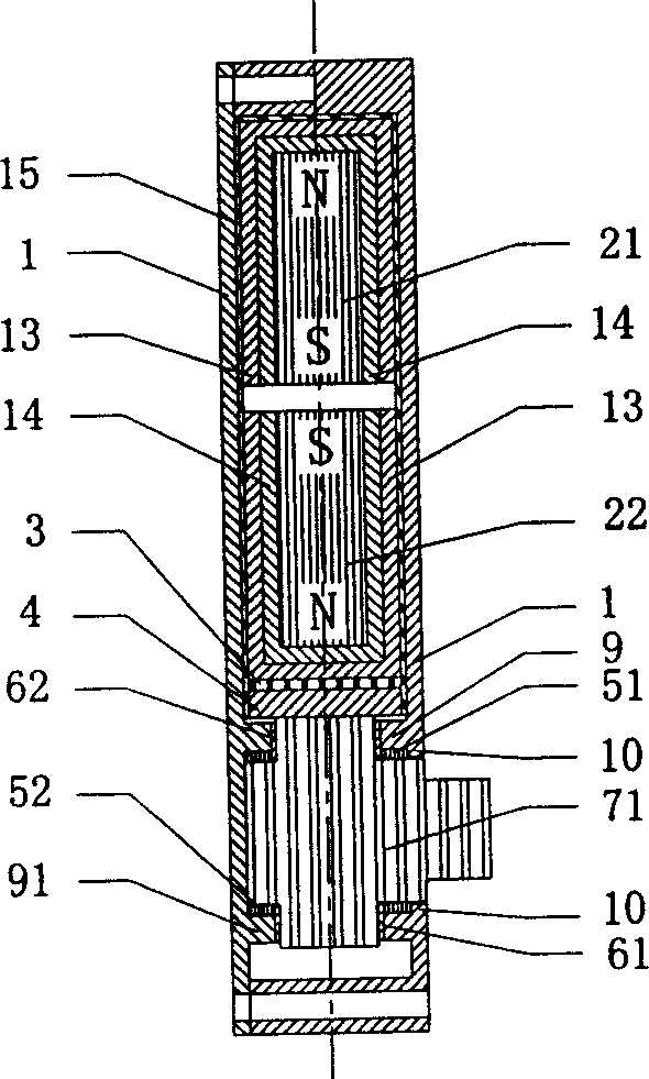
[0043] Such as Figure 1 to Figure 8 As shown in the structure, the longitudinal repulsion type strong magnetic force flap bed hinge of the present embodiment comprises a housing 1, a magnetic isolation cover 13, a positioning cover 14, an installation cover 15 with a cover claw 151 at the opening, two powerful magnets 21, 22, a Rotating supporting shaft 71 and door-shaped movable frame 4, described powerful magnet 21,22, rotating supporting shaft 71 are installed in the shell 1, wherein each described powerful magnet 21,22 is stacked and placed on the upper end of shell 1 successively, and The same pole is opposite between adjacent powerful magnets 21,22, and magnetic isolation cover 13 puts positioning cover 14, and positioning cover 14 puts powerful magnets 21,22, then packs in the installation cover 15 successively, and door type movable frame 4 also Put it into the installation cover 15 and seal the cover mouth of the installation cover 15, turn the cover claws 151 inward...
Embodiment 2
[0049] Such as Figure 8 ~ Figure 11 The structure shown is the second embodiment of the present invention. What is different from the first embodiment above is that the strong magnet in this embodiment includes three pieces 21, 22, and 23, and a magnetic isolation ring 16 and a positioning ring 17 are added. Cover 13 is put on positioning cover 14, and positioning cover 14 is put on powerful magnet 21,22, and magnetic isolation ring 16 is put on locating ring 17, and locating ring 17 is put on strong magnet 23, then is packed in the installation cover 15 successively, and door type activity Frame 4 also packs into the cover mouth of installation cover 15 and seals the cover mouth of installation cover 15, and cover claw 151 is inwardly folded, and magnetic isolation cover 13, positioning cover 14, magnetic isolation ring 16, positioning ring 17, powerful magnet 21, 22,23 4 claws of the door type movable frame are buckled in the installation cover 15.
Embodiment 3
[0051] Such as Figure 12 to Figure 17 The structure shown is the third embodiment of the present invention, and it differs from the first embodiment above in that: there is no movable frame in this embodiment, and the rotating support shafts with positioning blocks in the middle are a pair of 71a, 71b. The corresponding axle sleeve seats are also set as a pair of 9a, 91a, 9b, 91b; a gear pair transmission mechanism is established at a position adjacent to the pair of positioning blocks 73a, 73b, and the gear pair transmission mechanism includes a driving wheel 75 and a For the driven wheels 81, 82, a pair of driven wheels 81, 82 are respectively fixedly arranged on two rotating support shafts 71a, 71b, and the driving wheel 75 meshes with the two driven wheels 81, 82. The housing 1 is provided with The driving wheel shaft sleeve 9c, 91c, the driving wheel 75 is installed on the driving wheel shaft sleeve 9c, 91c by the driving gear shaft 74 thereon; an adjustment pad 3 is arr...
PUM
 Abstract
Description
Claims
Application Information
 - R&D
- Intellectual Property
- Life Sciences
- Materials
- Tech Scout
- Unparalleled Data Quality
- Higher Quality Content
- 60% Fewer Hallucinations
Browse by: Latest US Patents, China's latest patents, Technical Efficacy Thesaurus, Application Domain, Technology Topic, Popular Technical Reports.
© 2025 PatSnap. All rights reserved.Legal|Privacy policy|Modern Slavery Act Transparency Statement|Sitemap|About US| Contact US: help@patsnap.com