Vacuum cleaner having a blower capsule

A technology for vacuum cleaners and fans, which is applied in the installation of vacuum cleaners, motor fan components, household appliances, etc. It can solve the problems of the smooth wall of the flow channel, etc., and achieve the effect of reducing the types of parts and sealing costs

Inactive Publication Date: 2010-06-09
BSH BOSCH & SIEMENS HAUSGERAETE GMBH
View PDF4 Cites 0 Cited by
  • Summary
  • Abstract
  • Description
  • Claims
  • Application Information

AI Technical Summary

Problems solved by technology

The disadvantage of this fixing is that the inner housing enclosure must be fixed to the outer housing enclosure in a separate assembly step
This construction not only requires an additional assembly step, but also the flow channel cannot be formed with largely smooth walls, since the existing assembly gaps form disturbing edges for the air flow

Method used


Image

  • Vacuum cleaner having a blower capsule
  • Vacuum cleaner having a blower capsule
  • Vacuum cleaner having a blower capsule

Examples


Embodiment Construction

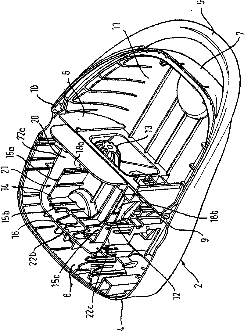
[0026] An embodiment of a vacuum cleaner according to the invention has a housing 1 with a bottom housing 2 in the figure 1 shown in . The base housing 2 is designed in the form of a wall and has a base 3 and a surrounding housing wall 4 . The housing wall 4 extends substantially vertically upwards starting from an edge region of the base 3 . At a front end of the base housing 1 , on the outer side of the housing wall 4 , a handle 5 is integrally formed on the base housing 2 . A partition wall 6 is arranged in the interior of the base housing 2 approximately midway between the front end 7 of the base housing 2 and a rear end 8 of the base housing 2 . Partition wall 6 from figure 1 A first side wall section 9 , shown at the front center left, extends as far as a second side wall section 10 , shown at the rear right of the housing wall 4 . The partition wall 6 divides the bottom housing 2 into a front dust collection chamber 11 and a rear fan chamber 12 . The partition wa...


PUM


Abstract

The invention relates to a vacuum cleaner comprising a housing (1) and an exhaust opening (36) that is fluidically connected to an overpressure side of a motor/blower unit (27), which is surrounded byan insulating capsule (71) and which is placed inside a blower housing (12), via a duct (21) that has a duct section (20, 28), which is arranged while extending between the insulating capsule (71) and the motor/blower housing (12). The aim of the invention is to obtain a fluidically optimized duct (21) between the insulating capsule (71) of the motor/blower unit (27) and of a housing part (12) with simple means whose production and assembly are cost-effective. To this end, the invention provides that at least one capsule part (14, 30) of the insulating capsule (71) is joined to a housing part, particularly of the blower housing (12), while forming a single piece. The largely prevents the formation of perturbing edges due to assembly gaps, and the vacuum cleaner can be cost-effectively produced and assembled with a reduced variety of parts.

Description

technical field [0001] The invention relates to a vacuum cleaner. Background technique [0002] Known from DE 41 00 858 A1 is a vacuum cleaner with a fan assembly, which is surrounded by an inner housing enclosure, which itself is inserted into an outer housing while keeping the flow chamber unchanged. A free cavity is formed between the housing enclosure and the housing. In this case, the air flow generated by the fan package flows through the flow chamber to an outlet provided on the housing. The fan unit is completely enclosed by means of an inner pot-shaped housing enclosure and an outer housing enclosure surrounding the housing enclosure, the outer housing enclosure consisting of two pot-shaped housing shells. The inner housing envelope is fixed in the outer housing envelope by means of profiled rails formed on an outer wall of the inner housing envelope. The disadvantage of this attachment is that the inner housing envelope must be attached to the outer housing enve...

Claims


Application Information

Patent Timeline
Patent Type & Authority Patents(China)
IPC IPC(8): A47L9/00A47L9/22
CPCA47L9/22A47L9/0081
Inventor E·博特R·伊利希A·尼德格塞斯
Owner BSH BOSCH & SIEMENS HAUSGERAETE GMBH
Why Eureka
Try Eureka