Fixed-type constant-velocity universal joint

A constant velocity universal joint, fixed technology, applied to elastic couplings, mechanical equipment, couplings, etc., can solve the problems of reduced strength of external joint components, increased load, and reduced wall thickness of external joint components. , to achieve the effect of large steering angle, small steering radius and improved safety

Active Publication Date: 2006-09-27
NTN CORP
View PDF1 Cites 12 Cited by
  • Summary
  • Abstract
  • Description
  • Claims
  • Application Information

AI Technical Summary

Problems solved by technology

[0006] While each of the fixed constant velocity universal joints described in the above publications has inner and outer joint members characterized by tapered track grooves that allow for greater joint operating angles, the current joint The trend towards light weight and compact structure limits the outer diameter of the outer joint member, and if

Method used


Image

  • Fixed-type constant-velocity universal joint
  • Fixed-type constant-velocity universal joint
  • Fixed-type constant-velocity universal joint

Examples


Embodiment Construction

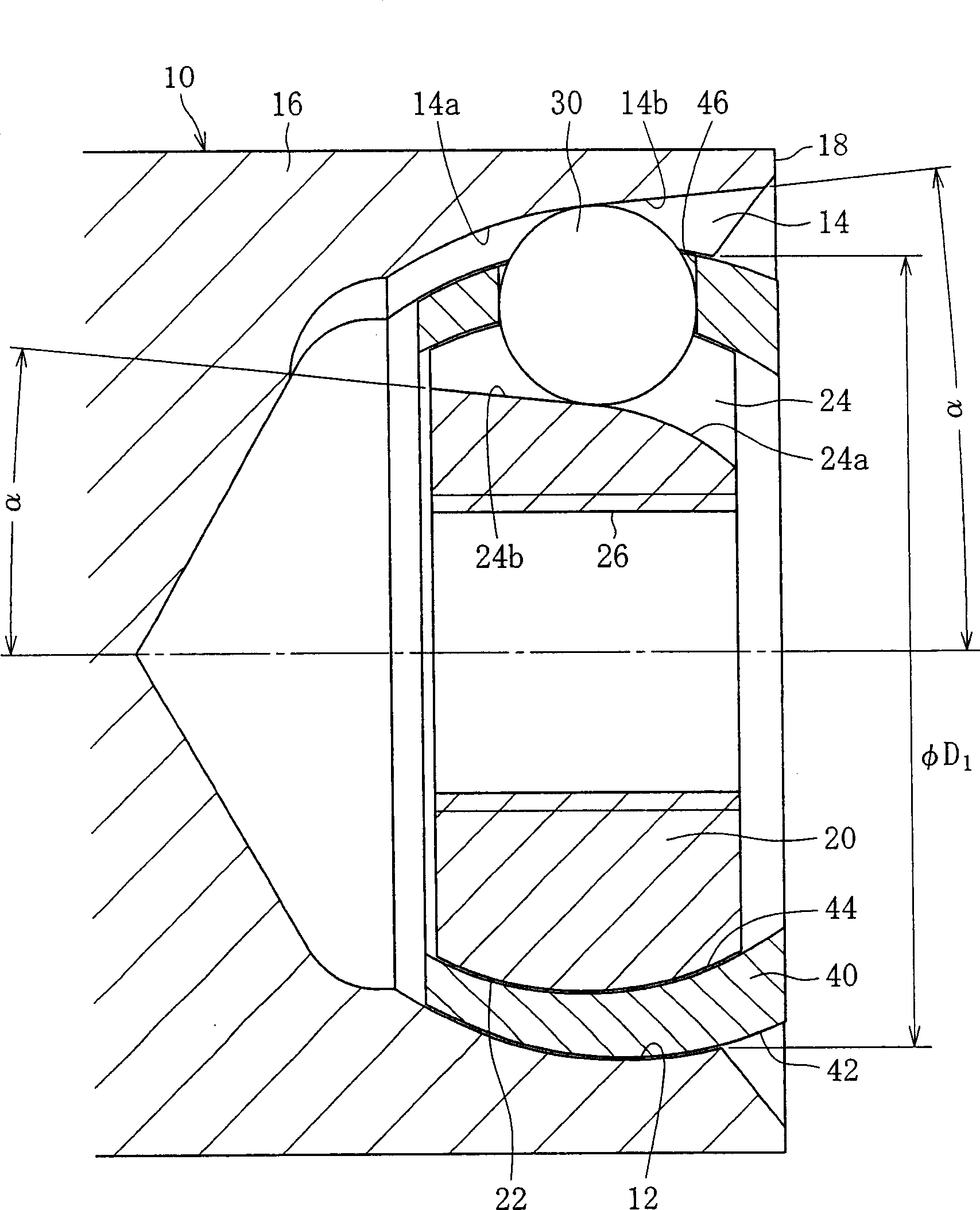
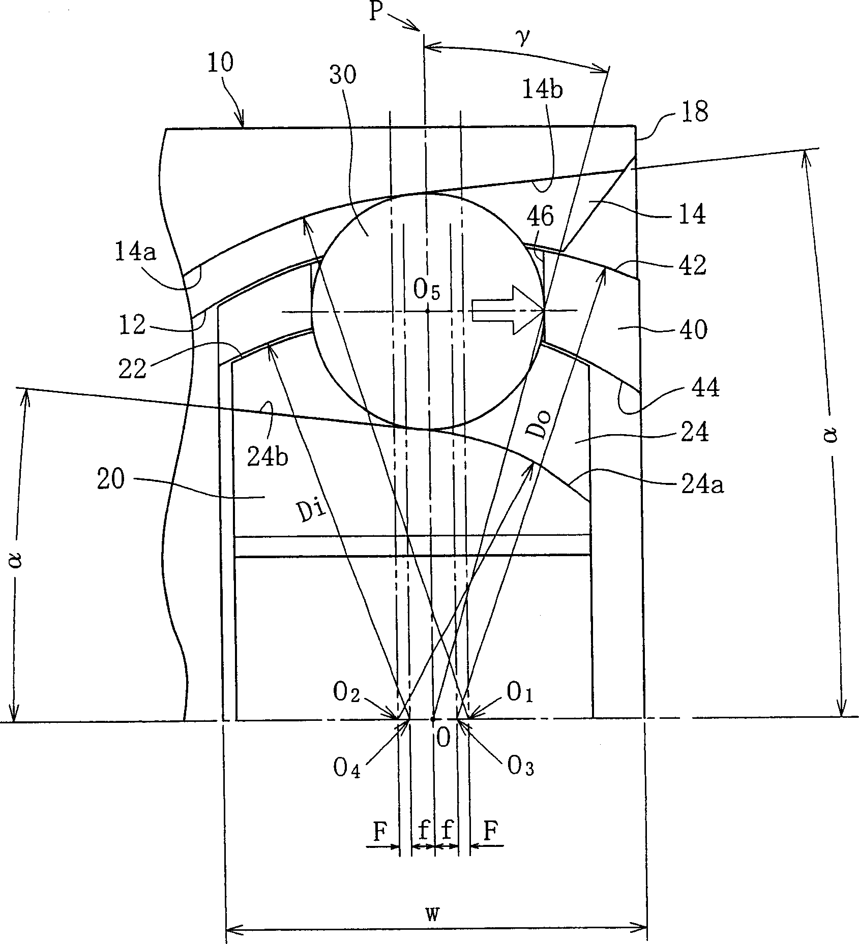
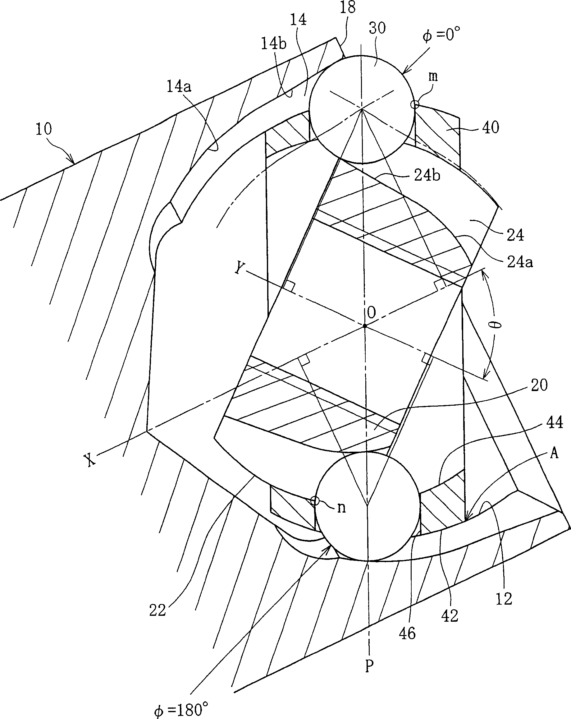
[0149] refer to figure 1 , The fixed constant velocity universal joint includes an outer ring 10 , an inner ring 20 , balls 30 and an isolation ring 20 . The fixed constant velocity universal joint connects the two shafts that need to be connected. For example, a driven shaft (not shown) is connected to the outer ring 10 and a driving shaft is connected to the outer ring so that torque is transmitted at a constant velocity from the driving shaft to the driven shaft when the two shafts are at an angle to each other. figure 1 Represent the state when the working angle θ formed by the rotating shaft X of the outer ring 10 and the rotating shaft Y of the inner ring 20 is 0°, and image 3 Indicates the state of the working angle θ at its maximum value.

[0150] The outer ring 10 as an outer joint member is composed of a mouth 16 and a stem (not shown) connected to the drive shaft in a torque-transmitting manner. Mouth 16 is essentially a cup with an open end and has a spherica...


PUM


Abstract

Internal dimensions for fixed-type constant velocity universal joints are defined to optimize the geometry of the components of the joints and to readily achieve a larger operating angle of the joints. In the joint, the track grooves of an outer ring and an inner ring are tapered by an angle not exceeding 12 DEG . The ratio (f/PCR) of the cage offset amount f to PCR is greater than 0 and smaller than or equal to 0.12. The ratio (Do/d) of the cage outer diameter (Do) to the ball diameter (d), the ratio (t/d) of the cage wall thickness (t) to the ball diameter (d), and the ratio (w/d) of the cage width (w) to the ball diameter (d) are such that 3.9<=Do/d<=4.1, 0.31<=t/d<=0.34, and 1.8<=w/d<=2.0, respectively. The end of the spherical outer surface of the cage adjacent to the open end is axially extended, and the end of the spherical inner surface of the cage adjacent to the open end is tapered so that the tapered surface has an increasing diameter toward the end of the spherical outer surface adjacent to the open end. Part of the spherical outer surface of the cage is cut on the open end side of pockets, and the outer diameter of the cage across the two opposing planer cut faces is smaller than the spigot diameter of the outer ring.

Description

technical field [0001] The invention relates to a fixed constant velocity universal joint. Constant velocity joints are used for power transmission in automobiles and various industrial machinery, and transmit torque from a driving shaft to a driven shaft at a constant angular velocity. Two types of constant velocity universal joints are known: the fixed type, which allows only angular displacements, and the slidable type, which allows both angular and axial displacements. Background technique [0002] A typical fixed constant velocity universal joint includes the following components: an outer joint member connected to a driving or driven shaft in a torque-transmitting manner; an inner joint member connected to a driven or driving shaft in a torque-transmitting manner; a plurality of balls between the inner and outer joint members to transmit torque; and a cage retaining the balls within the bisecting section of the corner between the driving and driven shafts. [0003] R...

Claims


Application Information

Patent Timeline
IPC IPC(8): F16D3/22F16D3/2233
Inventor 星野学中川亮登根宏菅沼和三郎
Owner NTN CORP
Why Eureka
Try Eureka