LED reflection cover manufacturing method

A technology of light-emitting diodes and manufacturing methods, applied in the direction of electrical components, circuits, semiconductor devices, etc., can solve problems such as easy generation of air bubbles, failure to meet customer needs, and inability to accurately control the amount of glue to achieve the effect of reducing air bubbles

Inactive Publication Date: 2006-09-27
EVERLIGHT ELECTRONICS
View PDF0 Cites 0 Cited by
  • Summary
  • Abstract
  • Description
  • Claims
  • Application Information

AI Technical Summary

Problems solved by technology

The dispensing method of this kind of reflective cover is usually unable to accurately control the amount of glue, and the speed is slow and easy to generate air bubbles
In order to meet the needs of mass production and quality assurance, the above methods may not meet the needs of customers

Method used


Image

  • LED reflection cover manufacturing method
  • LED reflection cover manufacturing method
  • LED reflection cover manufacturing method

Examples


Embodiment Construction

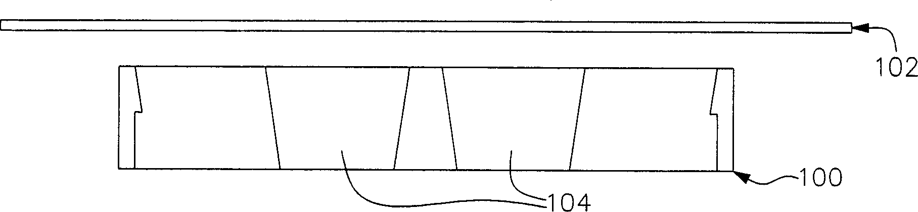
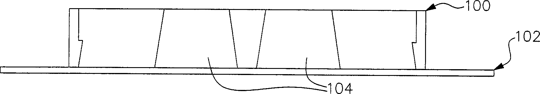
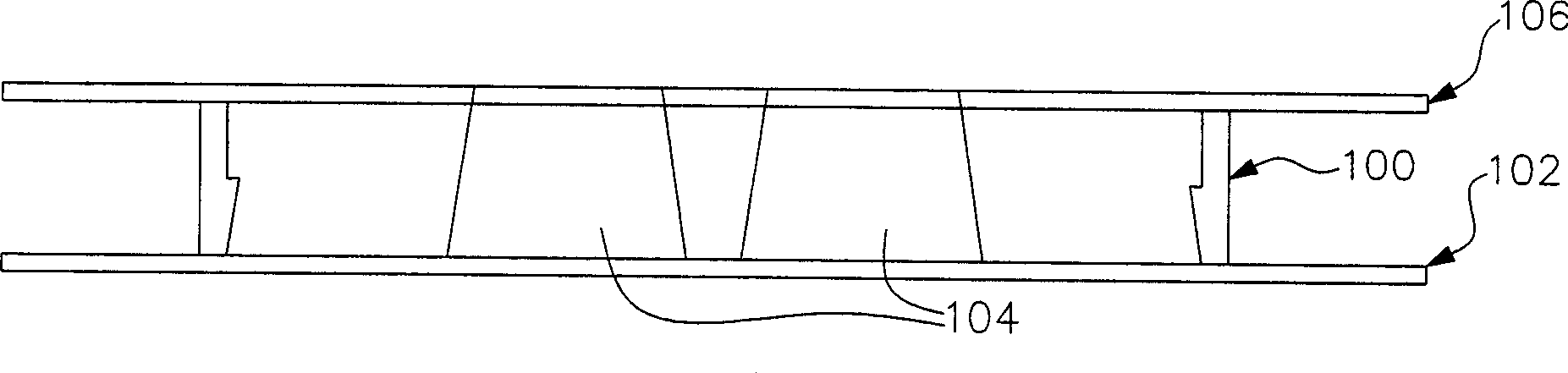
[0022] In order to solve the shortcomings of the known manufacturing method of the reflective cover that the amount of glue cannot be accurately controlled, the speed is slow, and bubbles are easily generated, the present invention proposes an improved manufacturing method of the reflective cover to overcome the above-mentioned problems. In this method, the reflective cover is designed as the upper half of the reflective cover and the lower half of the reflective cover, and the transparent glue is brushed into the hollow hole of the upper half of the reflective cover by brushing glue in the vacuum chamber. Finally, the upper half of the reflective cover and the lower half of the reflective cover are combined into a complete reflective cover.

[0023] Please refer to Figures 1A-1H , which represent the manufacturing steps of a light emitting diode reflective cover according to a preferred embodiment of the present invention. Figure 1A It shows the upper half 100 of a reflecti...


PUM


Abstract

This invention relates to a light emitting diode reflection cover making method, which includes: designing a reflection cover into an upper part and a down part. Affixing a spoiler at the face of the upper part; putting a deflector up to the surface of the upper part, and making the surface up toward. Pasting the glue into the hollow hole of the upper part through the hole of the deflector; firing the upper part; at last joining the upper part and the down part into a complete reflection cover.

Description

technical field [0001] The invention relates to a method for manufacturing a reflective cover, in particular to a method for manufacturing a reflective cover suitable for light-emitting diodes. Background technique [0002] Light emitting diodes have been widely used in various lighting and display fields in recent years. When applying light-emitting diodes, a reflective cover (outer cover) is often added to protect and guide light. Therefore, each reflective cover has a part of light-transmitting glue, so that the LEDs covered thereunder can emit light through the part of light-transmitting glue. [0003] It is known that the light-permeable glue portion of the light-emitting diode reflective cover is manufactured by dispensing glue. In the process, a syringe is usually used to inject the colloid into the hollow hole of the reflective cover. The dispensing method of this reflective cover usually cannot accurately control the amount of glue and is slow and prone to air bu...

Claims


Application Information

Patent Timeline
Patent Type & Authority Applications(China)
IPC IPC(8): H01L33/00
Inventor 吴旭隆陈中裕
Owner EVERLIGHT ELECTRONICS
Why Eureka
Try Eureka