Binder and file

A technology for file folders and utensils, which is applied in the field of file folders, can solve the problems of reduced storage efficiency, easy elastic deformation, and increase in the size of the file folder F, and achieve the effect of improving reliability

Inactive Publication Date: 2006-09-27
KOKUYO CO LTD
View PDF0 Cites 7 Cited by
  • Summary
  • Abstract
  • Description
  • Claims
  • Application Information

AI Technical Summary

Problems solved by technology

And, only the portion of the plug T, especially the distance from the base end a2 of the binding member a to the front end a1 is larger than necessary, and when external force acts on the front end a1, b1 side, it is easy to produce elastic deformation. , so there is a tendency that the above-mentioned bad situation becomes more significant
[0008] In addition, when the binding tool A is installed on the cover body B to form the file folder F, as Figure 17 As shown, the shape of the top part T creates a useless space between the top cover B1 and the bottom cover B2, resulting in a decrease in storage efficiency and an unnecessary increase in the external dimensions of the file folder F.

Method used


Image

  • Binder and file
  • Binder and file
  • Binder and file

Examples


no. 1 Embodiment approach

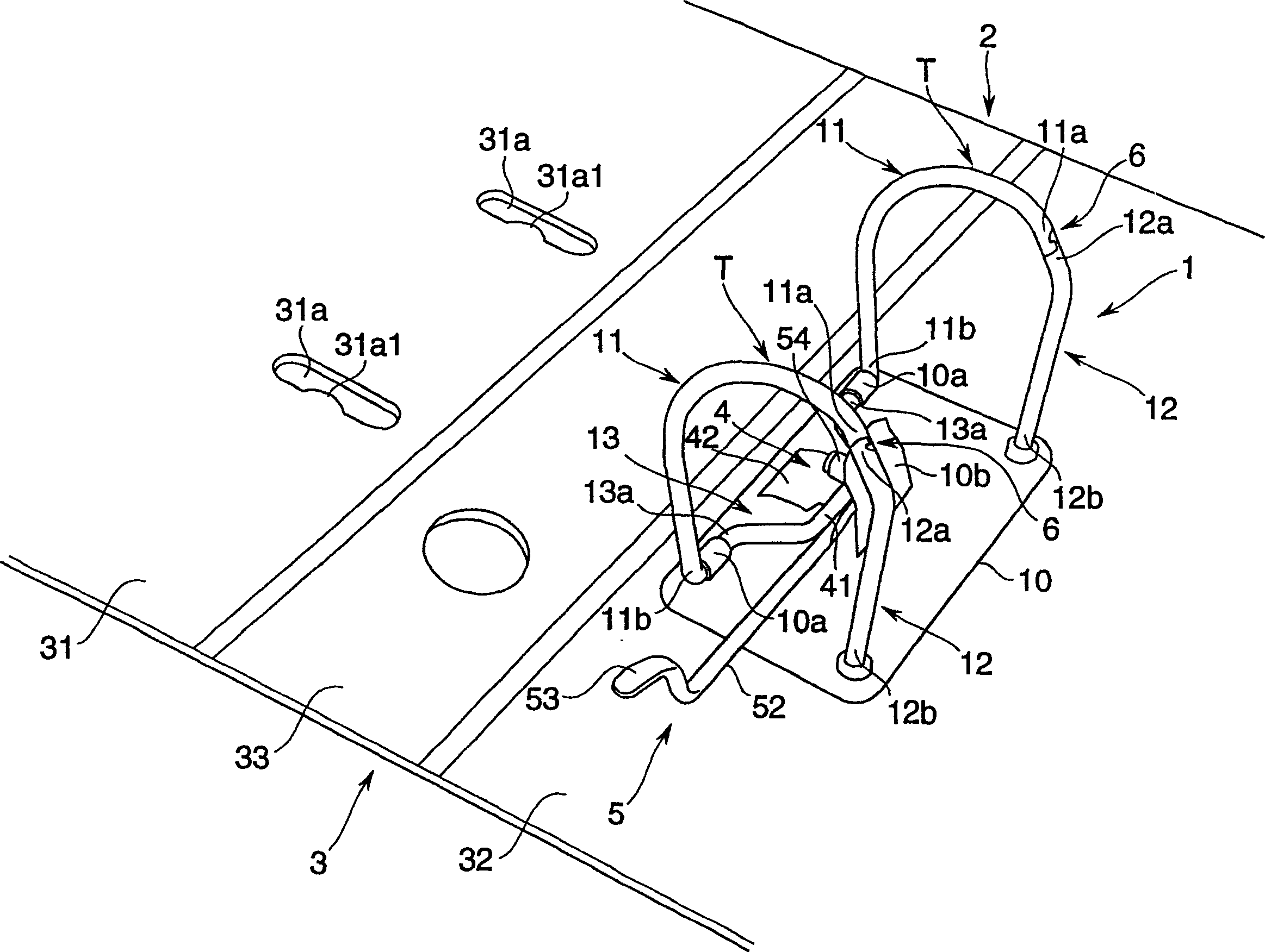
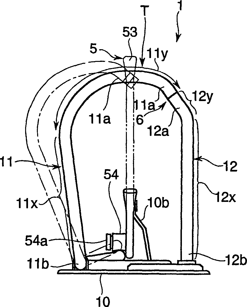
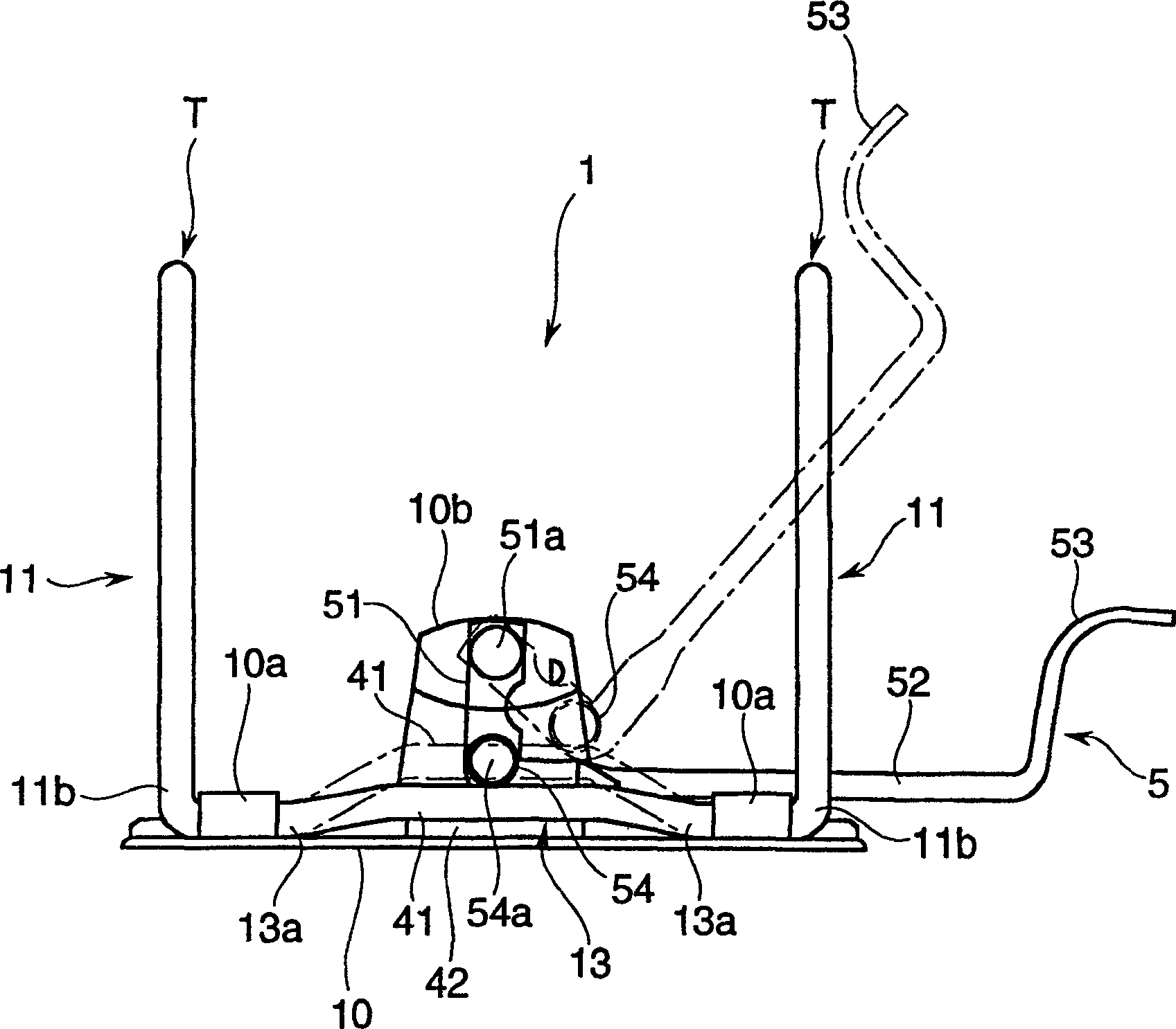
[0026] exist figure 1 In , a schematic perspective view of the main part of a file folder 2 equipped with a binding tool 1 is shown. Figure 2 to Figure 5In , the enlarged front view of the bookbinding tool 1 is shown, the left view is enlarged, the top view is enlarged, and the right view is enlarged. The folder 2 includes: a cover body 3 having a front cover 31 and a bottom cover 32 connected via a back cover 33 in the middle;

[0027] The binding tool 1 is equipped with a pair of first binding members 11, 11 on the base 10, and a pair of second binding members 12, 12 corresponding to these first binding members 11, 11. 1 The relative rotation of the binding member 11 and the second binding member 12, such as figure 2 etc., it becomes the structure which is closed or opened between the front-end|tip part 11a, 12a. In addition, this binding tool 1 is equipped with: an opening device 4, which applies force to the direction of opening between the front ends 11a, 12a of the...

no. 2 Embodiment approach

[0054] Figure 12 as well as Figure 13 The shown binding tool 101 of this embodiment basically has the same structure as the binding tool 1 of the above-mentioned first embodiment. Therefore, the same reference numerals are assigned to the same parts, and descriptions thereof will be omitted.

[0055] Therefore, in this binding tool 101, the shapes of the first and second binding members 111 and 112 are different from the shapes of the first and second binding members 11 and 12 constituting the binding tool 1 of the above-mentioned embodiment.

[0056] The first binding member 111 and the second binding member 112 are D-shaped members in a closed state. The first binding member 111 consists of an erecting area 111x that stands approximately vertically from the base 10 in the closed state, a bending area 111y that bends very slowly from the front end side of the erecting area 111x to the second binding member 112, and a The curved region 111y is configured with an extended ...


PUM


Abstract

A binder has a pair of first binding members and a pair of second binding members corresponding to the first binding members. When each of the fist binding members and corresponding each of the second binding members are relatively turned, tip portions of these first and second binding members are closed or opened, realizing a state where papers are bound or a state where papers are released from binding. The binder has opening means for applying a force in a direction where the tip portions of the first and second binding members are opened, and has an operation lever for relatively turning the first and second binding members against the opening means, and for retaining the tip portions at a closed position. The binder is characterized in that connection portions are provided in the tip portions The connection portions are connected to each other through temporary elastic deformation of at least either of the first binding members and the second binding members, and inhibit the opening operation of the tip portions by strengthening the connection by means of force applied by the opening means.

Description

technical field [0001] The present invention relates to a binding tool and a document file provided with an operation lever, which can be used well in offices and the like. Background technique [0002] For example, as this binding tool, as shown in Figure 15, known has the binding tool that is constituted in the following manner, promptly is provided with paired 1st binding member a, a on base e, and with these 1st binding member The paired second binding members b and b corresponding to a and a are closed or opened between the front ends a1 and b1 by the relative rotation of the first binding member a and the second binding member b respectively corresponding to each other. , to achieve the binding state or binding unbinding state for paper. In this binding tool A, it is equipped with: an opening device c, which applies a force in the direction of opening between the front ends a1, b1 of the first and second binding members a, b; and an operation lever d, which overcomes ...

Claims


Application Information

Patent Timeline
Patent Type & Authority Applications(China)
IPC IPC(8): B42F13/22B42F13/24
CPCB42F13/24
Inventor 坂上浩三
Owner KOKUYO CO LTD
Why Eureka
Try Eureka