Method and equipment for inspecting mounting accuracy of component

一种安装精度、检查方法的技术,应用在电气元件、电气元件等方向,能够解决夹具部件轮廓模糊、无法检测出部件安装位置等问题,达到清晰图像获取的效果

Inactive Publication Date: 2006-09-27
PANASONIC CORP
View PDF1 Cites 3 Cited by
  • Summary
  • Abstract
  • Description
  • Claims
  • Application Information

AI Technical Summary

Problems solved by technology

In this case, the shadow of the jig part may be formed on the surface of the substrate. In this case, the outline of the jig part may be blurred in the obtained image of the outline of the jig part. case, there is a problem that the correct part mounting position cannot be detected

Method used


Image

  • Method and equipment for inspecting mounting accuracy of component
  • Method and equipment for inspecting mounting accuracy of component
  • Method and equipment for inspecting mounting accuracy of component

Examples


Embodiment approach

[0082] Before continuing the description of the present invention, the same reference numerals are used for the same components in the drawings.

[0083] Hereinafter, embodiments of the present invention will be described in detail based on the drawings.

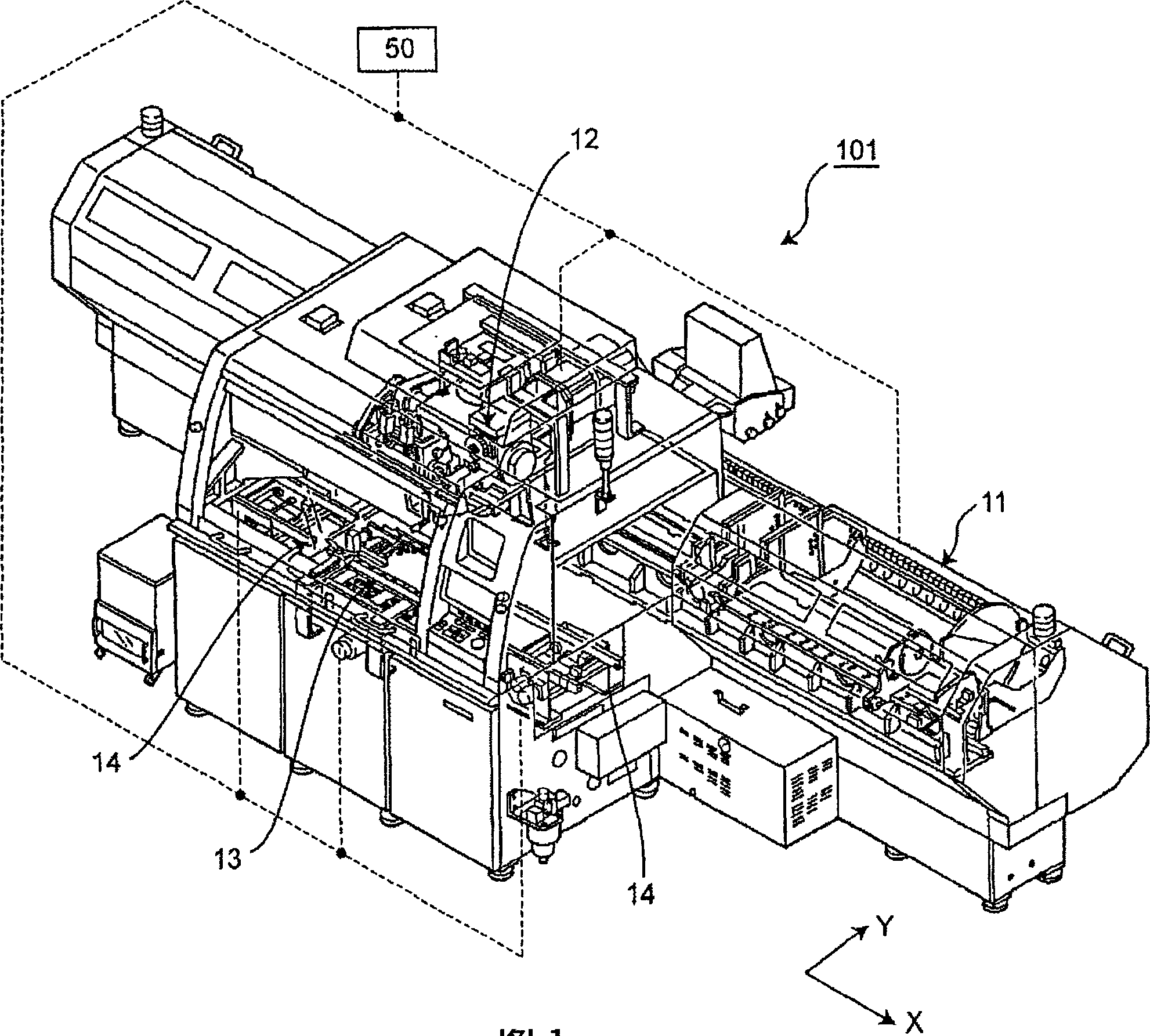
[0084] exist figure 1 3 is a perspective view showing an appearance of an electronic component mounting apparatus 101 as an example of a component mounting apparatus that performs inspection of component mounting accuracy according to Embodiment 1 of the present invention.

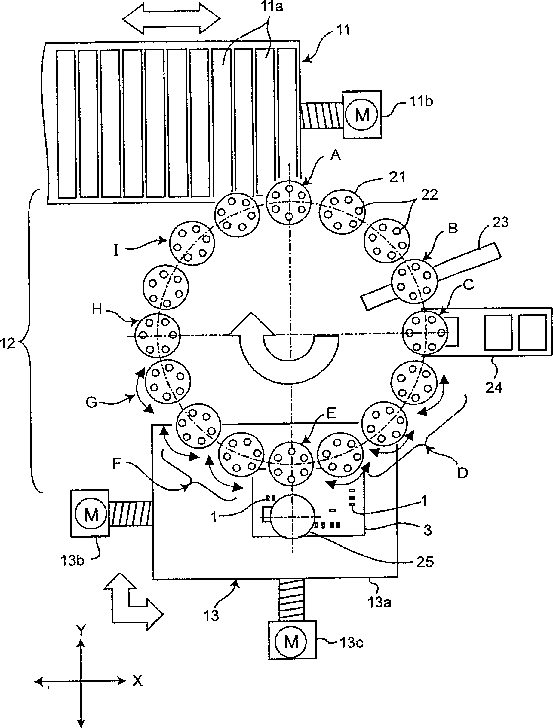
[0085] Such as figure 1 As shown, the electronic component mounting apparatus 101 is an apparatus for performing a component mounting operation for mounting a plurality of electronic components as an example of supplied components on a component mounting position on a substrate. The electronic component mounting apparatus 101 includes a component supply unit 11, a spindle device 12, an XY stage 13, and a substrate transfer device 14. The component supp...


PUM


Abstract

A component is mounted in a component mounting position on a component mounting-side surface of an inspection-use board which is formed from a light transmitting material and which has a reflecting surface disposed on a surface opposed to the component mounting side-surface in a state of facing the component mounting side-surface, light is applied to the component mounting-side surface of the inspection-use board, the applied light is transmitted through the component mounting-side surface and reflected on the reflecting surface so that an image of an outline of the component formed by reflected light coming from around the component through the component mounting-side surface is picked up, and a component mounting accuracy is calculated based on the image.

Description

technical field [0001] The present invention relates to a method and an inspection device for inspecting component mounting accuracy in component mounting in which a component held by a component holding member is mounted on a substrate. Background technique [0002] Conventionally, various detection methods and detection devices for such component mounting accuracy are known. For example, a method is performed in which a jig component for inspection produced with a higher dimensional tolerance than an electronic component handled in an electronic component mounting apparatus is placed on a substrate using a component suction nozzle in the electronic component mounting apparatus. Mounting detects the component mounting accuracy of the electronic component mounting device by detecting the amount of displacement of the mounting position of the jig component on the substrate (for example, refer to Patent Document 1). [0003] In such an inspection method, for example, after a ...

Claims


Application Information

Patent Timeline
Patent Type & Authority Applications(China)
IPC IPC(8): H05K13/08H05K13/04
CPCH05K13/08H05K13/0413H05K13/0812G01N21/8806
Inventor 酒井一信
Owner PANASONIC CORP
Why Eureka
Try Eureka