Cast-in-situ reinforced concrete slab

A reinforced concrete and cast-in-place technology, which is applied in the field of cast-in-place reinforced concrete slabs, can solve the problems of increasing the cross-sectional size of cast-in-place reinforced concrete ribs, increasing the amount of steel bars and concrete, and unreasonable mechanical properties, etc., and achieves convenient construction, Reduced cross-sectional size and excellent vibration resistance

Inactive Publication Date: 2006-10-04
邱则有
View PDF3 Cites 2 Cited by
  • Summary
  • Abstract
  • Description
  • Claims
  • Application Information

AI Technical Summary

Problems solved by technology

The solid formwork components disclosed above are used in densely ribbed slabs. They are both formwork components and prefabricated filling components. They have the characteristics of simple structure, high strength, excellent resistance to deformation and vibration, easy manufacture, and low cost. , but in the cast-in-place concrete floor, the cast-in-place reinforced concrete ribs formed between the solid formwork members are all rectangular cast-in-place reinforced concrete ribs, and their mechanical properties are not very reasonable, and it is often necessary to increase the cast-in-place reinforced concrete ribs. The cross-sectional size of the rib increases the amount of steel and concrete and increases the cost of the floor. Therefore, it is urgently needed to develop a new type of cast-in-place reinforced concrete slab.

Method used


Image

  • Cast-in-situ reinforced concrete slab
  • Cast-in-situ reinforced concrete slab
  • Cast-in-situ reinforced concrete slab

Examples


Embodiment Construction

[0044] The present invention will be further described below in conjunction with the accompanying drawings and embodiments.

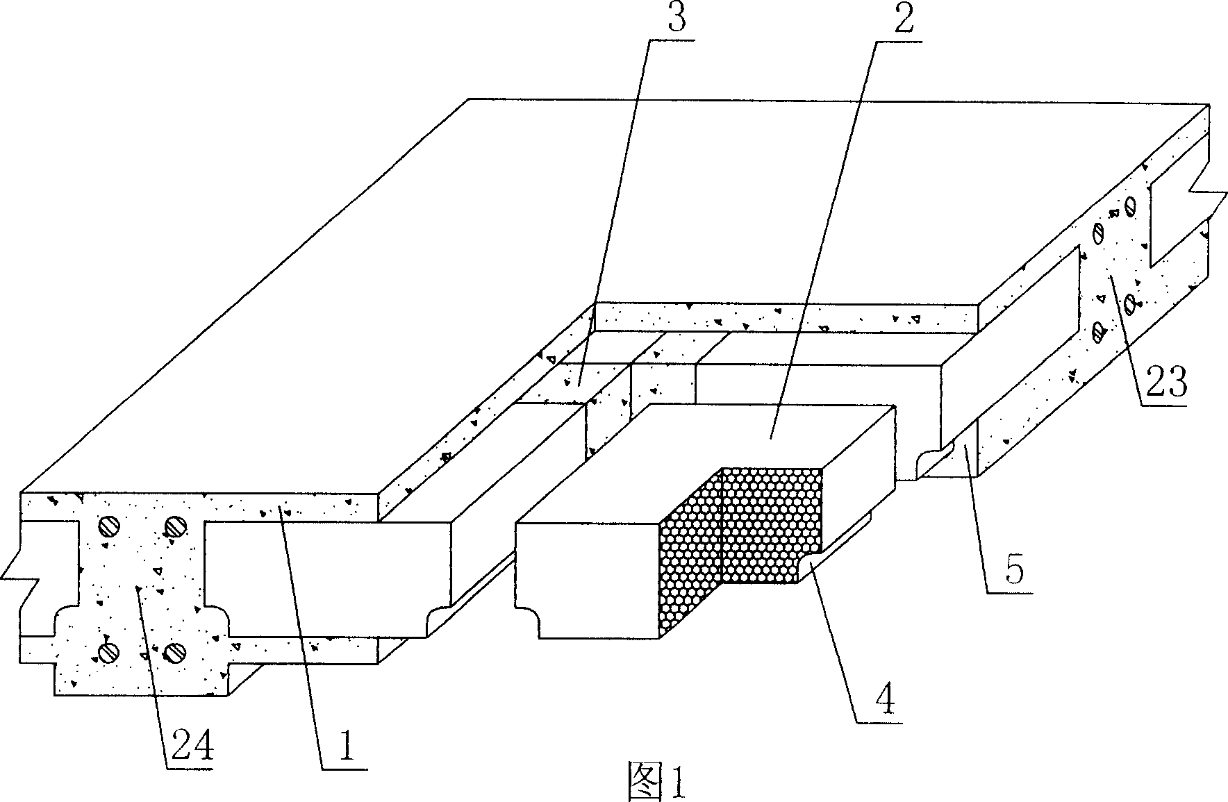
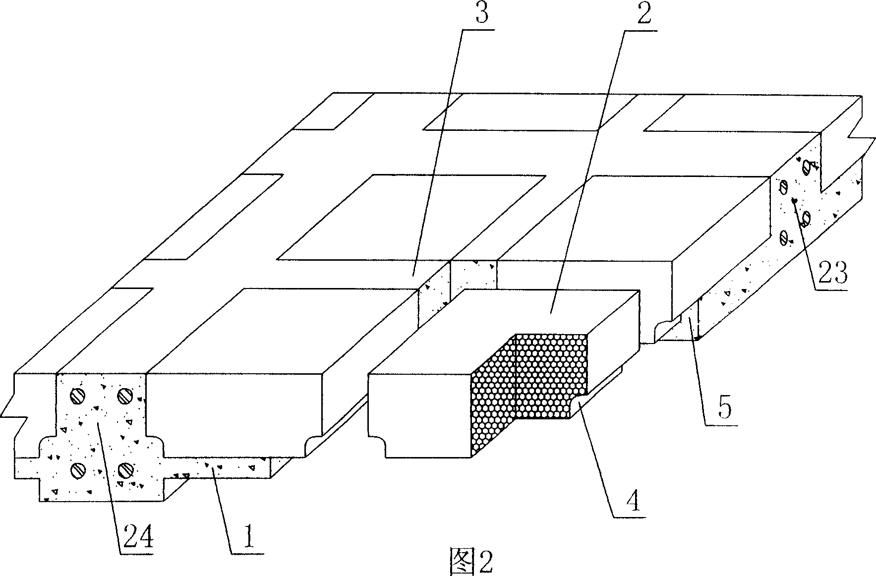
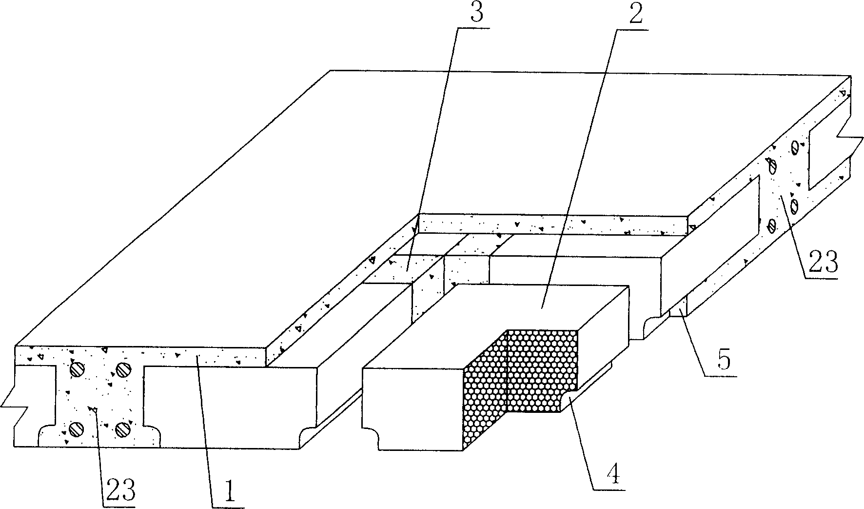
[0045] As shown in the accompanying drawings, the present invention includes reinforced concrete 1, polyhedral solid lightweight material formwork components 2, the formwork components 2 are wrapped in the reinforced concrete 1, the formwork components 2 are arranged alternately, and the cast-in-place reinforced concrete is formed between them The rib 3 is characterized in that at least one transverse corner of the lower part of the formwork member 2 is an inner corner 4, and the cast-in-place concrete at the inner corner 4 forms the flange 5 of the cast-in-place reinforced concrete rib 3, and the corresponding cast-in-place concrete The poured reinforced concrete rib 3 forms an inverted T-shaped rib. In each drawing, 1 is reinforced concrete, 2 is formwork member, 3 is cast-in-place reinforced concrete rib, 4 is inner corner, and 5 is flange. In the fo...


PUM


Abstract

Disclosed is a cast-in-situ reinforced-bar concrete slab, which comprises a reinforced-bar concrete (1) and polyhedral solid lightweight shuttering member (2), the shuttering member (2) is enclosed in the reinforced-bar concrete (1), and arranged alternatively, a cast-in-situ reinforced-bar concrete rib (3) is arranged between them, characterized in that least one of the transverse corners on the lower portion of the shuttering member (2) is configured to be an internal corner (4), the cast-in-situ reinforced wing rim (5) is formed on the cast-in-situ concrete position at the internal corner (4) position, a reversed T-shape rib is formed by the cast-in-situ reinforced bar concrete rib (3). The invention can be applied to cast-in-situ reinforced concrete or prestressed reinforcement concrete's storied-building roofings, house roofings, walls, foundation bedplates and bridges, especially for flat slabs.

Description

(1) Technical field [0001] The invention relates to a cast-in-place reinforced concrete slab. (2) Background technology [0002] At present, the cast-in-place reinforced concrete slab is a widely used floor structure, and the lightweight permanent tire mold filled therein has various hollow tubes and boxes, and the boxes are hollow or solid. For example, the patent No. ZL99249798.1, which the applicant applied for on November 29, 1999, is a utility model patent named "fiber-reinforced thin-walled member for reinforced concrete filling", which discloses a thin-walled formwork member, including an upper plate, The surrounding side walls, the lower bottom, and the upper plate, the surrounding side walls and the lower bottom form a polyhedral cavity. Another example is the patent No. ZL00203695.9 applied by Liang Jun, Shijiazhuang City, Hebei Province on February 23, 2000, and the name is called "combined concrete hidden rib floor cover plate" utility model patent, which disclo...

Claims


Application Information

Patent Timeline
Patent Type & Authority Applications(China)
IPC IPC(8): E04B5/36E04G11/36E04C5/00
Inventor 邱则有
Owner 邱则有
Why Eureka
Try Eureka