
Apparatus for controlling quantity of feeding oil of inverter compressor

A frequency conversion compressor and oil supply technology, applied in the field of frequency conversion compressors, can solve the problems such as the inability to compress the frequency conversion compressor, the reduction of the oil level, and the damage of the refrigerant.

Inactive Publication Date: 2006-10-04
LG ELECTRONICS INC
View PDF0 Cites 7 Cited by
  • Summary
  • Abstract
  • Description
  • Claims
  • Application Information

AI Technical Summary

Problems solved by technology

[0012] Since the oil level in the casing is lowered due to the discharge of excess oil, a sufficient amount of oil cannot be supplied to the compression parts, so that the inverter compressor cannot compress the refrigerant and is damaged

Method used


Image

  • Apparatus for controlling quantity of feeding oil of inverter compressor
  • Apparatus for controlling quantity of feeding oil of inverter compressor
  • Apparatus for controlling quantity of feeding oil of inverter compressor

Examples


Embodiment Construction

[0051] Hereinafter, an oil supply controller for an inverter compressor according to a preferred embodiment of the present invention will be described in detail with reference to the accompanying drawings.

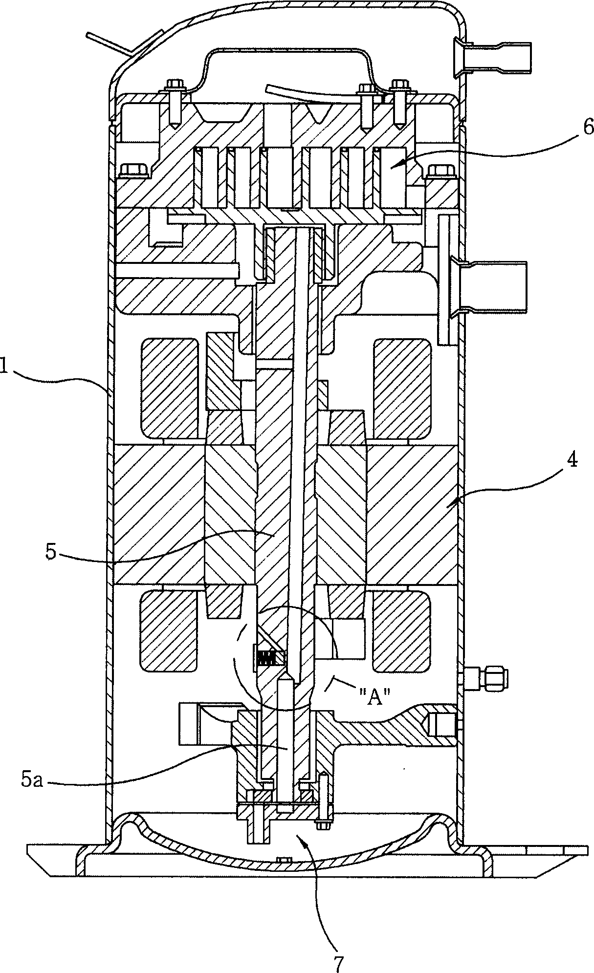
[0052] image 3 is a vertical sectional view showing an inverter compressor employing an oil supply controller of an inverter compressor according to a first preferred embodiment of the present invention, Figure 4 yes image 3 An enlarged view of part "A" in .

[0053] Such as image 3 and 4 As shown, the oil supply controller of the inverter compressor according to the first preferred embodiment of the present invention includes: a mounting hole 10 formed in the rotating shaft 5 to communicate with the oil passage 5a of the rotating shaft 5; a bypass passage 20 formed in the The rotating shaft 5 communicates with the front end of the installation hole 10 ; and the oil supply control component 30 is installed in the installation hole 10 . The oil supply control part ...


PUM


Abstract

An oil feed controller of an inverter compressor controls the quantity of feeding oil to prevent excess oil from being fed to a compression part when rotational speed of a rotation shaft is increased. The oil feed controller includes an installation hole formed in the rotation shaft to communicate with an oil passage of the rotation shaft, a bypass formed in the rotation shaft to communicate with the leading end of the installation hole, and an oil feeding controlling part installed in the installation hole to close the bypass when the rotation shaft rotates at low speed and to open the bypass when the rotation shaft rotates at high speed such that the quantity of oil ascending to the compression part through the oil passage is controlled.

Description

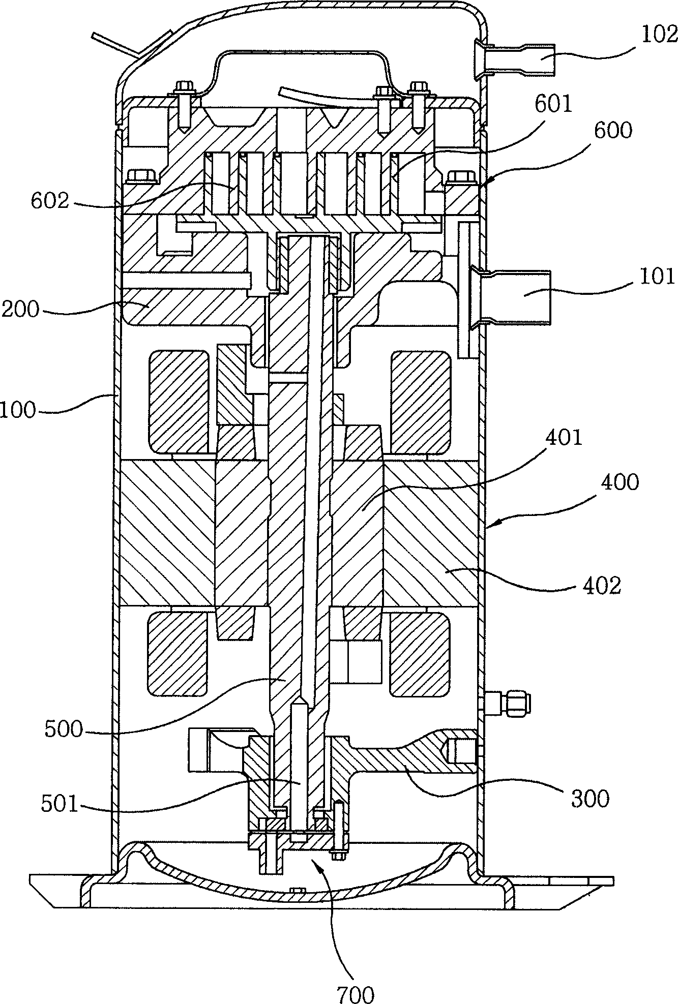
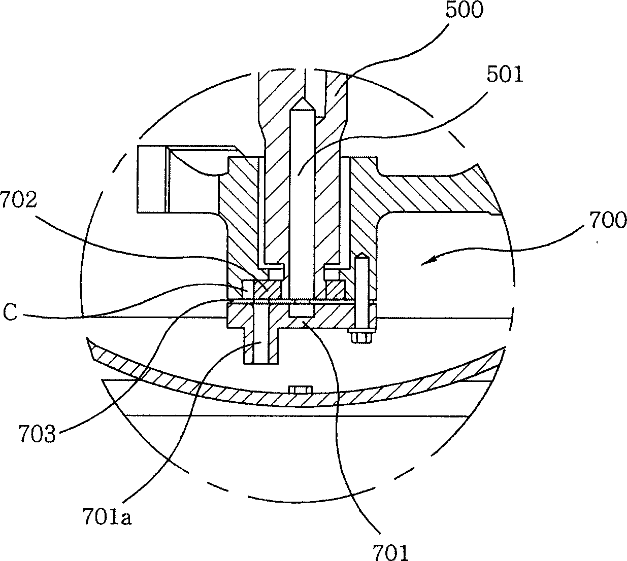
technical field [0001] The present invention relates to an inverter compressor, and more particularly, to an oil supply control device for an inverter compressor, which prevents excessive oil supply to the inverter compressor by controlling an oil supply amount when the rotation speed of a rotating shaft increases. Background technique [0002] figure 1 is a vertical sectional view showing a conventional inverter compressor, figure 2 yes figure 1 An enlarged view of part "A" in . [0003] Such as figure 1 and figure 2 As shown, a conventional variable frequency compressor includes: a casing 100 having a suction pipe 101 and a discharge pipe 102; a main frame 200 and an auxiliary frame 300 fixed to the upper side and the lower side of the casing 100; variable frequency drive components 400, which is installed between the main frame 200 and the auxiliary frame 300; the rotating shaft 500, which is rotated by the variable frequency drive part 400; and the compression par...

Claims


Application Information

Patent Timeline
IPC IPC(8): F04C28/00
CPCA45B9/04A63B29/08
Inventor 朴弘熙金明均刘东原郑哲守俞炳吉崔世宪
Owner LG ELECTRONICS INC
Learn More